Cell resuscitator
A resuscitator and cell technology, applied in the field of cell biology, can solve the problems of low degree of automation, difficult to accurately control cell recovery time and temperature, etc., to achieve dry and wet separation, improve quality and stability, and improve work efficiency. Effect
- Summary
- Abstract
- Description
- Claims
- Application Information
AI Technical Summary
Problems solved by technology
Method used
Image
Examples
Embodiment 1
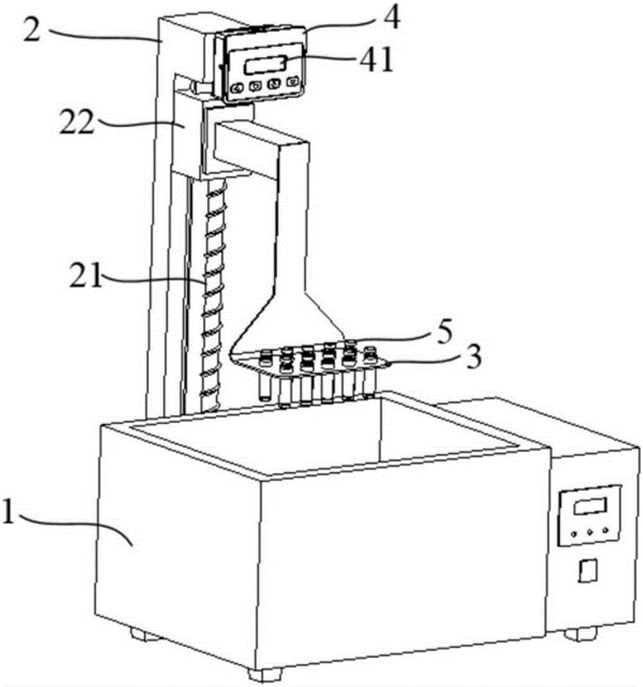
[0029] figure 1 A cell resuscitator is shown for rapidly reviving cells stored cold in liquid nitrogen. The present invention comprises a water bath 1, a lifting mechanism 2, a carrying device detachably arranged on the lifting mechanism 2, a controller 4 and a distance sensor (not shown in the figure).
[0030] In this embodiment, the lifting mechanism 2 is a screw lifter, including a motor (not shown in the figure), a screw rod 21 , and a slider mechanism 22 . The controller 4 is electrically connected with the lifting mechanism 2, and is used for controlling the movement of the lifting mechanism 2 and putting the carrying device into the water bath 1. The carrying device is a tray 3 , but is not limited to the tray 3 , and may be a clamp that can hold the cryopreservation tube 5 . Positioning holes are provided on the tray 3, and the tray 3 can be used to fix cryopreservation tubes 5 of different sizes in batches.
[0031] In this embodiment, the cell resuscitator furthe...
Embodiment 2
[0037] Embodiment 2 is substantially the same as Embodiment 1, as Figure 4 As shown, the difference is that the cell resuscitator also includes a first isolation sleeve 6 and a cover plate 7, the first isolation sleeve 6 is used to isolate the carrying device and the water bath 1, and the cover plate 7 is arranged on the lifting mechanism 2 and located on the carrying device The upper cover plate 7 matches the opening of the first isolation sleeve 6 , and the cover plate 7 and the first isolation sleeve 6 can form a sealed space. When performing cell recovery, the lifting mechanism 2 places the tray 3 with several cryopreservation tubes 5 in the first isolation sleeve 6, avoiding the direct contact between the cryopreservation tubes 5 and water, and when the lifting mechanism 2 moves to the lowest position, The cover plate 7 just covers the opening of the first isolation sleeve 6 and seals the cryopreservation tube 5 in a sealed environment, reducing the influence of external...
Embodiment 3
[0039] Embodiment 3 is substantially the same as Embodiment 1, as Figure 5 As shown, the difference is that the carrying device includes a plurality of second isolation sleeves 8, and the second isolation sleeves 8 are detachably arranged on the carrying device. The second isolation sleeve 8 is used to carry the cryopreservation tube 5 and to isolate the cryopreservation tube 5 from the water bath 1, avoiding the direct contact between the cryopreservation tube 5 and water, and realizing the dry-wet separation of the cryopreservation tube 5 and the water bath 1. The second spacer 8 is made of a material with excellent thermal conductivity, and its specifications are specially designed according to the specifications of the cryotubes 5. Each cryotube 5 corresponds to a spacer, so that it can take into account better heat conduction. In the experiment, the cryopreservation tube 5 was directly placed in the second isolation sleeve 8, and the controller 4 received the distance si...
PUM
 Abstract
Description
Claims
Application Information
 - Generate Ideas
- Intellectual Property
- Life Sciences
- Materials
- Tech Scout
- Unparalleled Data Quality
- Higher Quality Content
- 60% Fewer Hallucinations
Browse by: Latest US Patents, China's latest patents, Technical Efficacy Thesaurus, Application Domain, Technology Topic, Popular Technical Reports.
© 2025 PatSnap. All rights reserved.Legal|Privacy policy|Modern Slavery Act Transparency Statement|Sitemap|About US| Contact US: help@patsnap.com


