Tyre's inner tire mat belt installing machine
A technology for installing machines and tires, applied in tire installation, tire parts, transportation and packaging, etc., can solve problems such as difficulty in achieving long-term stable and efficient work, damage to tires and inner tube pads, and high requirements for mutual cooperation. , to achieve the effect of saving consumption, reducing volume, and simple loading method
- Summary
- Abstract
- Description
- Claims
- Application Information
AI Technical Summary
Problems solved by technology
Method used
Image
Examples
Embodiment 1
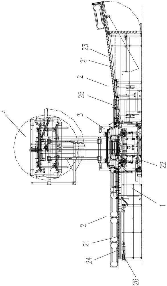
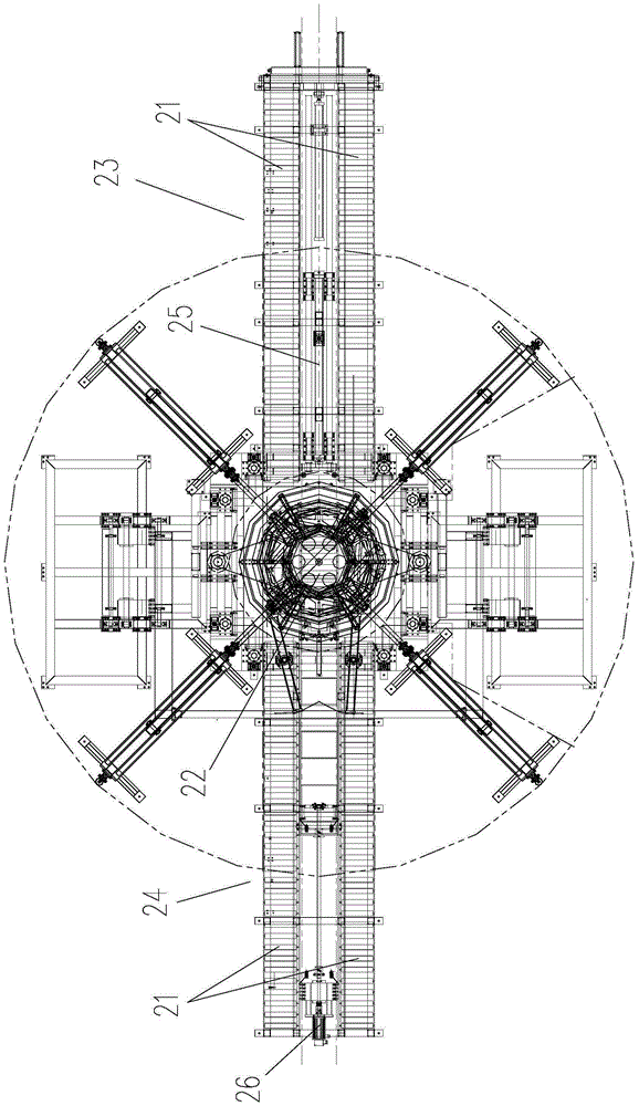
[0036] Such as Figure 1 to 5 As shown, the tire inner tube cushion belt installation machine includes a frame 1 on which a tire conveying device 2, a tire opening device 3 and a tire filling device 4 are installed.
[0037] The tire opening device 3 is located in the middle of the tire conveying device 2, and the tire filling device 4 is located above the tire opening device 3.
[0038] The tire conveying device 2 includes a conveying mechanism and a tire-feeding drive device. Two conveying mechanisms are arranged at intervals between the front and rear. The tire opening device 3 is located between the two conveying mechanisms.
[0039] The conveying mechanisms all include supporting rollers 21 fixed on the left and right sides of the frame 1 in parallel.
[0040] A feeding roller table 22 is installed between the supporting roller tables 21 of the conveying mechanism. The feeding roller table 22 is slidably installed on the corresponding frame 1, and the tire driving device 26 is in...
Embodiment 2
[0060] The structural composition of the second embodiment is basically the same as that of the first embodiment, the difference lies in:
[0061] The first conveying mechanism 23 is located on the front side, and the second conveying mechanism 24 is located on the rear side. The kick-out cylinder 25 is installed on the frame 1 between the supporting rollers 21 of the first conveying mechanism 23, and the feeding roller 22 is located in the second conveying. Between the supporting roller table 21 of the mechanism 24.
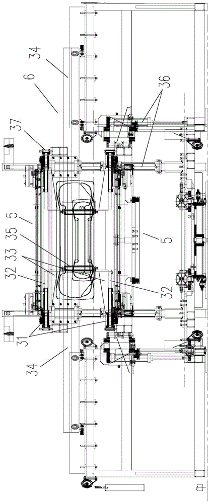
[0062] After the tire is installed and rotated, the tire is centered and fixed by the centering and fixing mechanism 6, and the flaring mechanism 5 is returned to its position. At this time, the tire is only centered and fixed by the centering and fixing mechanism 6. The piston rod kicked out of the cylinder 25 quickly pushes toward the tire, while the centering and fixing mechanism 6 returns to its position. The rapidly extending piston rod gives the tire a certain ...
Embodiment 3
[0065] The structure of the third embodiment is basically the same as that of the first embodiment, and the difference lies in:
[0066] A first drive plate 38 is mounted coaxially and rotatable on the first support plate 31. The first drive plate 38 is provided with a plurality of first guide grooves 39. The first guide grooves 39 gradually approach the first drive from the outer end to the inner end. In the center of the plate 38, the guide rods provided by the tyre claw 33 are located in the corresponding first guide groove 39.
[0067] The tire removal driving device is a tire removal motor, and the tire removal motor drives the first drive plate to rotate 38 to slide the tire removal pawl 33.
[0068] A second drive plate 48 is coaxially rotatably mounted on the second support plate 42. The second drive plate 48 is provided with a plurality of second guide grooves 49. The second guide grooves 49 gradually approach the second drive from the outer end to the inner end. The center...
PUM
 Abstract
Description
Claims
Application Information
 - R&D
- Intellectual Property
- Life Sciences
- Materials
- Tech Scout
- Unparalleled Data Quality
- Higher Quality Content
- 60% Fewer Hallucinations
Browse by: Latest US Patents, China's latest patents, Technical Efficacy Thesaurus, Application Domain, Technology Topic, Popular Technical Reports.
© 2025 PatSnap. All rights reserved.Legal|Privacy policy|Modern Slavery Act Transparency Statement|Sitemap|About US| Contact US: help@patsnap.com


