


Quick Research
Generate reliable direction feasibility study reports for your R&D in just a few steps.

Technical Q&A
Discover and master advanced knowledge NOW. Basics, ideas, possibilities, all at once.

Find Solutions
As an expert in R&D theories, this can generate solutions to your technical problems instantly.

Evaluate Feasibility
Analyze your overall solution with one click, know your potential R&D risks in advance.

Monitor Landscape
Get weekly tech updates, stay abreast of the latest tech innovations and key insights.
Drum type burr removing machine
A technology of deburring machine and deburring mechanism, which is applied to surface polishing machine tools, machine tools suitable for grinding workpiece edges, grinding machines, etc. It can solve problems such as single structure, cumbersome workpiece transportation operations, time-consuming and labor-intensive safety, and achieve Convenient centralized management, convenient collection and transportation, and low manufacturing cost
- Summary
- Abstract
- Description
- Claims
- Application Information
AI Technical Summary
Problems solved by technology
Method used
Image

Examples
Embodiment 1
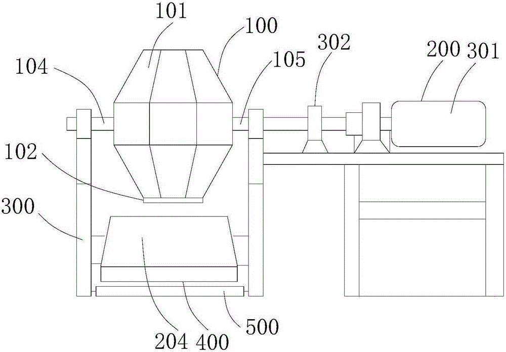
[0046] see Figure 1-5 ,本实施例提供了一种滚筒式去毛刺机,包括去毛刺机构100、传动机构200以及安装架300,其中:
[0047] 所述去毛刺机构100以及所述传动机构200分别安装在所述安装架300上,所述去毛刺机构100与所述安装架300转动连接,所述去毛刺机构100的输入端固定连接所述传动机构200的输出端,所述传动机构200驱动所述去毛刺机构100相对于所述安装架300转动;
[0048] 所述滚筒式去毛刺机还包括导料板400以及冷却槽500,所述导料板400位于所述去毛刺机构100的下方,所述冷却槽500位于所述导料板400的下方,且所述导料板400以及所述冷却槽500分别可拆卸连接所述安装架300;所述导料板400的出料端位于所述冷却槽500的槽体内。
[0049] 本发明提供的滚筒式去毛刺机,该设备结构简单合理,加工制造方便,制造成本低;同时,工件在去毛刺完成后,便于集中管理,收集与运输方便,同时工件的收集与运输省时省力,具体如下:
[0050] 该去毛刺机包括去毛刺机构100以及传动机构200,所述去毛刺机构100以及所述传动机构200分别安装在安装架300上,去毛刺机构100能够相对于所述安装架300转动,即,所述传动机构200的输出端连接所述去毛刺机构100的输入端,驱动所述去毛刺机构100转动,去毛刺机构100转动,带动其腔体内的工件以及去毛刺的物质一起做旋转运动,将工件的毛刺去除。同时,该去毛刺机还包括导料板400以及冷却槽500,所述导料板400位于所述去毛刺机构100的下方,去毛刺结构工作完毕后,将去毛刺机构100的出料口对准导料板400即可,工件能够安全的落在导料板400上,不需要人工拿着装载工具放置在出料口,节省了人力物力;进一步的,所述冷却槽500位于所述导料板400的下方,所述导料板400的出料端位于所述冷却槽500的槽体内,工件从导料板400出来,落入冷却槽500内,便于对工件进行处理,即可以清洗工件表面的杂质以及在冷却槽500内储存冷却液,实现工件的快速冷却,便于工件的后续加工。
[0051] 工件进行去毛刺时,工件与去毛刺物质相互摩擦,毛刺与工件主体的接触较为松动,长时间摩擦后毛刺能够从工件上脱落,完成去毛刺过程。毛刺去除后,需要将工件以及去毛刺物质一起从去...
Embodiment 2
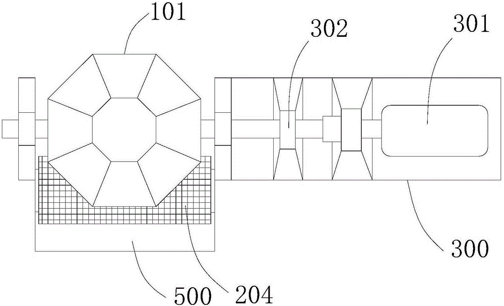
[0063] see Figure 6-7 ,本实施例也提供了一种滚筒式去毛刺机构100,该实施例是在实施例一的技术方案的基础上的进一步改进,实施例一描述的技术方案同样适用于本实施例,实施例一描述的技术方案不再重复描述,具体如下:
[0064] 所述冷却槽500内设置有滤网201,所述滤网201位于所述导料板400与所述冷却槽500之间,所述滤网201可拆卸连接所述冷却槽500,便于将杂质与工件分隔开,工件的后续处理更加方便。
[0065]In a preferred solution of this embodiment, the material guide plate 400 includes two opposite side plates 202 and a bottom plate 203 between the two side plates 202, the bottom plate 203 is fixedly connected to the two side plates 202 , the two side plates 202 are detachably connected to the installation frame 300 ; the height of the end of the bottom plate 203 close to the cooling tank 500 is lower than the height of the end of the bottom plate 203 away from the cooling tank 500 . Under the action of its own gravity, the workpiece can be directly transported from the discharge end of the material guide plate 400 to the cooling tank 500, saving the steps of manually pushing the workpiece and the deburring material to the cooling tank 500, and the opera...
PUM
 Abstract
Description
Claims
Application Information
 - R&D Engineer
- R&D Manager
- IP Professional
- Industry Leading Data Capabilities
- Powerful AI technology
- Patent DNA Extraction
Browse by: Latest US Patents, China's latest patents, Technical Efficacy Thesaurus, Application Domain, Technology Topic, Popular Technical Reports.
© 2024 PatSnap. All rights reserved.Legal|Privacy policy|Modern Slavery Act Transparency Statement|Sitemap|About US| Contact US: help@patsnap.com