pad

A technology of percussion pads and percussion surfaces, which is applied to electro-acoustic musical instruments and instruments, and can solve the problems of not being able to fully improve percussion feeling and quietness, small deformation, adverse effects on percussion feeling and quietness, etc.

Active Publication Date: 2018-12-28
YAMAHA CORP
View PDF8 Cites 0 Cited by
  • Summary
  • Abstract
  • Description
  • Claims
  • Application Information

AI Technical Summary

Problems solved by technology

[0004] However, in the above-mentioned conventional percussion pads, the elastic deformation of the thin-walled portion is mainly simple elongation and the amount of deformation is small when striking, so the percussion feeling and quietness cannot be sufficiently improved.
[0005] In addition, if the thin-walled portion cannot be elastically deformed sufficiently, the pad portion itself is likely to be partially deformed, resulting in a rebound force, which adversely affects the impact feeling and quietness.

Method used


Image

  • pad
  • pad
  • pad

Examples


Embodiment Construction

[0012] Hereinafter, a percussion pad according to an embodiment of the present invention will be described with reference to the drawings.

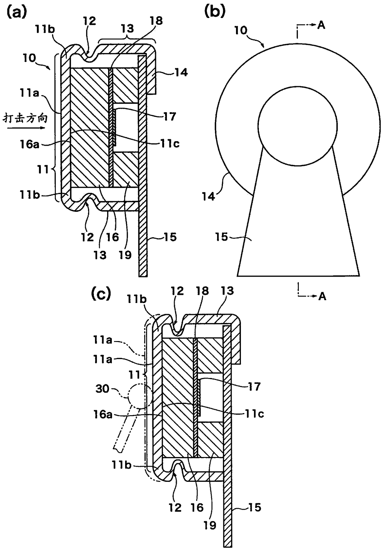
[0013] figure 1 (a) is a schematic sectional view showing a non-strike state of the striking pad according to one embodiment of the present invention, figure 1 (b) is said figure 1 (a) Rear view of the pad, figure 1 (c) means that the figure 1 (a) Schematic cross-sectional view of the striking state of the pad. figure 1 (a) means along figure 1 (b) A-A line section.

[0014] It is assumed that the percussion pad 10 of the present invention is suitable for electronic percussion instruments, preferably a kick drum, but not limited thereto. For example, it can also be configured as a special pad for practice.

[0015] The pad 10 is attached to a drum body 15 . The drum body 15 is supported on an unillustrated stand installed on the ground or the like.

[0016] The pad 10 has a pad portion 11 , a connection portion 12 , a support port...


PUM


Abstract

The invention provides a striking pad. A pad part (11) and a connection part (12) of the striking pad (10) are made of soft materials such as rubber materials with elasticity. A peripheral part (11b) of the connection pad part (11) and a support part (13) are connected by the connection part (12), so that the pad part (11) is supported on the support part (13). The connection part (12) forms a thin wall which forms a bending shape and is bent to the inner diameter direction of the support part (13) under a non-striking state. When a striking face of the pad part (11) is struck, the connection part (12) elastically deforms mainly through compression or bending in elongation, compression and bending. The connection part (12) allows at least the peripheral part (11b) of the pad part (11) to displace towards the striking direction.

Description

technical field [0001] The present invention relates to a percussion pad, which is suitable for percussion instruments and the like, and has a pad portion having a striking surface to be struck. Background technique [0002] A percussion pad suitable for a percussion instrument or the like is supported on a supporting portion such as a drum frame or a resonance box, and the striking surface of the pad portion is struck by the striking member. A structure in which a pad portion is supported by a support portion via a thin portion as shown in Patent Document 1 below is known as a prior art. When struck, the pad sinks in the striking direction due to the elasticity of the thin-walled portion. [0003] Patent Document 1: (Japanese) Unexamined Patent Publication No. 2004-287356 [0004] However, in the above-mentioned conventional percussion pads, the elastic deformation of the thin-walled portion is mainly simple elongation and the amount of deformation is small at the time of...

Claims


Application Information

Patent Timeline
Patent Type & Authority Patents(China)
IPC IPC(8): G10H1/00G10H1/32G10H3/14
Inventor 金山惠美西田贤一
Owner YAMAHA CORP
Why Eureka
Try Eureka