Polarimeter for teaching experiment

A polarimeter and experimental technology, applied in the field of polarimeter, can solve the problems of cumbersome operation, low measurement accuracy and large volume of the polarimeter, and achieve the effects of high measurement accuracy, convenient all-round adjustment, and reduced error

Inactive Publication Date: 2015-12-23
CHENGDU GERUISI CULTURAL COMM
View PDF5 Cites 0 Cited by
  • Summary
  • Abstract
  • Description
  • Claims
  • Application Information

AI Technical Summary

Problems solved by technology

[0002] Polarimeters have been widely used in teaching experiments. With the rapid development of social economy, the whole society and the country attach great importance to education issues. Science and technology are the primary productive forces. Educational projects are urgently needed in all walks of life. During the entire education process All kinds of educational equipment are needed. In the entire educational structure, the state attaches great importance to the education of physics and mechanics, so the state also advocates that relevant technical personnel can create more and better physics teaching equipment. It is one of the professional measuring equipment of polarimeter to measure the optical rotation of the substance. By measuring the optical rotation of the sample, it can analyze and determine the concentration, content and purity of the substance. It is widely used in pharmaceuticals, drug inspections, sugar, food, spices, Monosodium glutamate and chemical, petroleum and other industrial production, scientific research and teaching departments are used for laboratory analysis or process quality control. However, most current polarimeters for physics teaching have certain defects in structural design, and the measurement accuracy of these polarimeters is low. , bulky and cumbersome to operate

Method used


Image

  • Polarimeter for teaching experiment

Examples


Embodiment Construction

[0013] The present invention will now be described in further detail in conjunction with the accompanying drawings, which are simplified schematic diagrams, only schematically illustrating the basic structure of the present invention, and therefore only show the configurations related to the present invention.

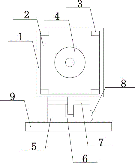
[0014] Such as figure 1 The preferred embodiment of the shown teaching experiment polarimeter of the present invention comprises a test case body 1, a built-in half-wave plate 2 in the test case body 1, and the half-wave plate 2 is embedded and arranged on the test case body 1, and the half-wave plate 2 is close to four There is a boss 3 at the top corner, and the boss 3 is clamped on the half-wave plate 2. The light source 4 is installed in the middle of the half-wave plate 2. The bottom of the test box body 1 is provided with a rotating rod 5. The top of the rotating rod 5 is connected to the test box. The body 1 is rotatably connected, and its bottom is connected to...


PUM


Abstract

The present invention discloses a polarimeter for a teaching experiment. The polarimeter comprises an experimental box body which is internally provided with a half-wave plate which is embedded in the experimental box body. The half-wave plate is provided with bosses close to four corners. The bosses are clamped in the half-wave plate. The middle part of the half-wave plate is equipped with a light source. The bottom of the experimental box body is provided with a rotation rod. The top of the rotation rod is rotatingly connected to the experimental box body, and the bottom of the rotation rod is connected to a rotation base. A focusing handle is vertically arranged in the rotation rod and is at the bottom of the experimental box body. The focusing handle is connected to the half-wave plate through a fine adjustment tube. The rotation rod is internally and horizontally equipped with a limit plate. The focusing handle goes through the limit plate, and the side of the rotation rod is connected to a rotation block. According to the polarimeter, the all-round adjustment of an angle can be facilitated, at the same time the adjustment is flexible, the structure is simple, an experimental phenomena can be showed visually, thus students can accept the principle of the experimental phenomena well, the measurement precision is high, and an error is reduced greatly.

Description

technical field [0001] The invention relates to a polarimeter, in particular to a polarimeter for teaching experiments. Background technique [0002] Polarimeters have been widely used in teaching experiments. With the rapid development of social economy, the whole society and the country attach great importance to education issues. Science and technology are the primary productive forces. Educational projects are urgently needed in all walks of life. During the entire education process All kinds of educational equipment are needed. In the entire educational structure, the state attaches great importance to the education of physics and mechanics, so the state also advocates that relevant technical personnel can create more and better physics teaching equipment. It is one of the professional measuring equipment of polarimeter to measure the optical rotation of the substance. By measuring the optical rotation of the sample, it can analyze and determine the concentration, conte...

Claims


Application Information

Patent Timeline
IPC IPC(8): G09B23/22
Inventor 曾玥
Owner CHENGDU GERUISI CULTURAL COMM
Why Eureka
Try Eureka