A Method of Dynamically Adjusting Radar Angle Error

A technology of dynamic adjustment and radar angle, applied in the field of radar, can solve the problems of limited filter processing effect and large filter response time, achieve good control stability and angle measurement performance, weaken antenna oscillation, and shorten the effect of filter response time

Active Publication Date: 2018-01-19
SHANGHAI RADIO EQUIP RES INST
View PDF5 Cites 0 Cited by
  • Summary
  • Abstract
  • Description
  • Claims
  • Application Information

AI Technical Summary

Problems solved by technology

Such as non-patent literature, literature 1 "tracking radar angle error analysis and filter design" ("ship electronic countermeasures", No.4, 1995) and literature 2 "discussion on airborne radar angle error processing" ("Gansu Science and Technology" , Vol. 30 No.17, Sept.2014), Document 3 "Research on Control Accuracy of Radar Servo System" ("Harbin Institute of Technology Dissertation", 2009), in which Document 1 uses Kalman filter to analyze the extracted radar angle error Processing, document 2 uses alpha-beta filtering to process the extracted radar angle error, document 3 conducts a more in-depth study on the filtering of radar angle error, in addition to introducing the above two filtering methods, it also describes the PID filter in detail, And compared and analyzed their advantages and disadvantages, the filter processing of radar angle error can improve the control performance of servo mechanism and radar angle measurement performance to a certain extent, but there is a large filter response time, and in the receiving signal-to-noise ratio The effect of filtering is limited when the measurement error of low radar angle error is large

Method used


Image

  • A Method of Dynamically Adjusting Radar Angle Error
  • A Method of Dynamically Adjusting Radar Angle Error
  • A Method of Dynamically Adjusting Radar Angle Error

Examples


Embodiment Construction

[0022] The present invention will be further elaborated below by describing a preferred specific embodiment in detail in conjunction with the accompanying drawings.

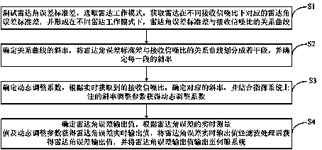
[0023] Such as figure 1 As shown, a method for dynamically adjusting the radar angle error includes the following steps:

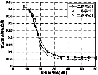
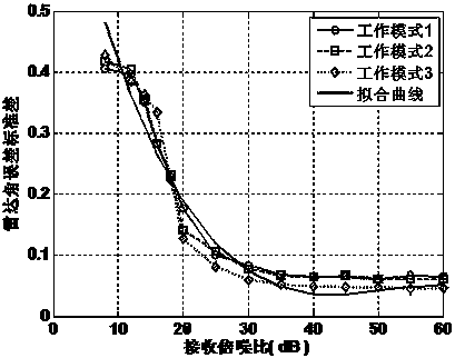
[0024] S1. Test the standard deviation of the radar angle error, select the radar working mode, obtain the corresponding radar angle error standard deviation of the radar under different receiving signal-to-noise ratios, and form the radar angle error standard deviation and receiving signal-to-noise ratio under different radar working modes relationship curve.

[0025] In this implementation, preferably, in the microwave test compact field, adjust the position of the target simulator so that the simulated target is located at the position of the radar (1°, 1°), and after the radar tracks the target stably in the state of working mode 1, Adjust the transmission power of the radar test signal...


PUM


Abstract

The invention discloses a method for dynamically adjusting the radar angle error, comprising the following steps: obtaining the radar angle error standard deviation corresponding to the radar under different receiving signal-to-noise ratios, and forming the ratio of the radar angle error standard deviation and the radar angle error standard deviation under different radar working modes The relationship curve of the received signal-to-noise ratio; divide the relationship curve between the standard deviation of the radar angle error and the received signal-to-noise ratio into several sections, and determine the slope of each section; determine the corresponding slope according to the received signal-to-noise ratio obtained in real time, and The dynamic adjustment coefficient is obtained by combining the slope adjustment parameters noted on the command system; the real-time output value of the radar angle error is obtained according to the real-time measurement value of the radar angle error and the dynamic adjustment parameters. The present invention utilizes the signal-to-noise ratio information of the received signal to dynamically adjust the radar angle error output to the servo system, which can weaken the antenna oscillation when the signal-to-noise ratio is low, completely eliminate the violent oscillation of the antenna, and avoid losing targets due to radar angle flicker at close range It can improve the radar tracking performance and system stability.

Description

technical field [0001] The invention relates to the technical field of radar, in particular to a method for dynamically adjusting radar angle errors. Background technique [0002] The radar angle error is the angle error information formed by the difference between the antenna pointing and the target line of sight direction extracted by processing the echo signal. The continuous tracking radar sends the extracted radar angle error to the closed-loop angle servo system to drive the antenna beam to move with the target movement, so as to achieve precise tracking of the target. [0003] Due to the existence of factors such as noise and angular flicker, the angular error extracted by the radar changes randomly, especially when the signal-to-noise ratio of the received signal is low, the radar angular error changes greatly, which often causes the servo system to control the antenna violently. Affect the tracking accuracy of the radar and the stability of the system. [0004] Th...

Claims


Application Information

Patent Timeline
Patent Type & Authority Patents(China)
IPC IPC(8): G01S7/40G01S13/68
CPCG01S7/4026G01S13/68G01S7/403G01S7/4034
Inventor 江利中邹波吉峰黄勇衡燕裘寒青
Owner SHANGHAI RADIO EQUIP RES INST
Why Eureka
Try Eureka