
Spatial two-point calibration projection based base coordinate system calibration method of coordinated robot

A technology of base frame and calibration method, which is applied in the field of collaborative robot base frame calibration based on spatial two-point projection

Active Publication Date: 2015-12-23
ZHEJIANG UNIV
View PDF3 Cites 10 Cited by
  • Summary
  • Abstract
  • Description
  • Claims
  • Application Information

AI Technical Summary

Problems solved by technology

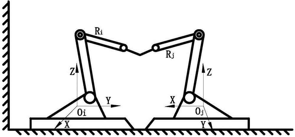
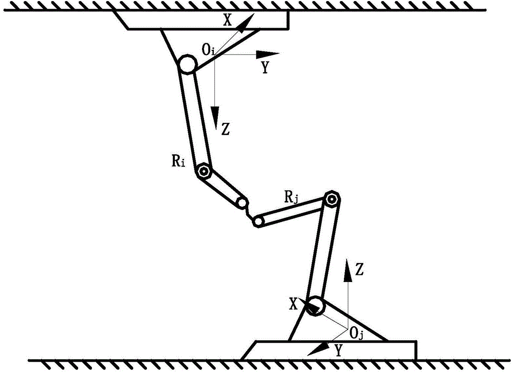
[0004] In order to solve the calibration problem of the base frame of the multi-robot collaborative operation system, the object of the present invention is to propose a method for calibrating the base frame of the collaborative robot based on two-point projection in space. The z-axis of the base frame is perpendicular to the same plane The collaborative robot system does not need to add external precision sensing instruments and other measurement tools. It is simpler, more efficient, and more feasible. By allowing two robots with a collaborative operation relationship to shake hands in any posture to reach two calibration points in space, Based on the geometric constraint relationship of spatial projection, the relative pose of the robot base frame can be calibrated quickly and accurately

Method used


Image

  • Spatial two-point calibration projection based base coordinate system calibration method of coordinated robot
  • Spatial two-point calibration projection based base coordinate system calibration method of coordinated robot
  • Spatial two-point calibration projection based base coordinate system calibration method of coordinated robot

Examples


Embodiment Construction

[0065] The present invention will be described in further detail below in conjunction with the accompanying drawings and specific embodiments.

[0066] The basic principle of the present invention mainly lies in: arbitrarily determine two non-repetitive calibration points on different sides of the line connecting the origins of the base coordinates of the two cooperative robots and in the overlapping public work space, and by constructing the action of shaking hands of the robots, the two The end point of the collaborative robot arrives at the calibration point at the same time in any spatial position, and the collaborative robot system and the determined calibration point are projected on the X-Y, Y-Z plane, and the projected geometric constraint relationship diagram of the plane is established, so as to obtain the base of the collaborative robot The rotation and translation offsets of the relative poses of the coordinate system, and finally obtain the pose transformation matr...


PUM


Abstract

The present invention discloses a spatial two-point calibration projection based base coordinate system calibration method of coordinated robot. The method is as below: grouping all robots by minimal calibration unit; establishing a two robot base coordinate system; on both sides of the base standard two robots each department to determining a calibration point respectively at two sides of a connection line of the origins of the base coordinate system of each robot; contacting the end points of the robots in a handshake way at the calibration points to obtain joint angle information; establishing a D-H coordinate system to calculate an end posture matrix, an end RPY angle and coordinates of the two calibration points under the base coordinate system; projecting the robots and the calibration points, calculating three matrices, combining the three matrices to obtain a relative pose transform matrix, and repeating the steps in each of the minimal calibration unit to complete calibration of base coordinate system for coordinated robot. The present invention relies on spatial projection robotic to fully utilize facilities of the robot, and has the advantages of less spatial point calibration, effective reduction of cost, significant reduction of time, efficiency improvement, and wide range of adaption.

Description

technical field [0001] The present invention relates to a robot calibration method, in particular to a collaborative robot base coordinate system calibration method based on spatial two-point projection, and relates to the complex flexibility of many industrial robots such as welding, handling, engraving and spraying in industrial production. system manufacturing field. Background technique [0002] With the advent of the Industry 4.0 era, in many fields such as the processing, assembly and handling of large and complex parts, welding, spraying and engraving without fixture systems, traditional single robots can no longer meet their processing requirements well, so the research has The multi-robot system with collaborative operation relationship will become an inevitable trend of industrial development. When a multi-robot system works collaboratively, it needs to calibrate and confirm the relative position of each robot in advance, that is, it is necessary to accurately cal...

Claims


Application Information

Patent Timeline
IPC IPC(8): G01C25/00
CPCG01C25/00
Inventor 王进王伟陆国栋吴潮华
Owner ZHEJIANG UNIV
Learn More