Pneumatic-electronic control system of filter element welding machine

An electronic control system, welding machine technology, applied in the direction of fluid pressure actuation system components, welding equipment, auxiliary welding equipment, etc., can solve the problems of complex structure, low production efficiency, poor welding quality, etc. Effect

Active Publication Date: 2015-12-23
溧阳市森德电器有限公司
View PDF6 Cites 1 Cited by
  • Summary
  • Abstract
  • Description
  • Claims
  • Application Information

AI Technical Summary

Problems solved by technology

[0002] At present, the most used at home and abroad is the disposable paper filter. The filter element of the filter is composed of a filter paper tube, a central net tube, upper and lower end caps, etc. The cover is bonded together, there are disadvantages such as degumming and short service life
In response to the above-mentioned degumming phenomenon, some manufacturers make the upper and lower end caps with epoxy resin material, pour the epoxy resin into the mold, and naturally solidify with the filter paper cylinder and the central mesh cylinder as a whole. Although the degumming phenomenon has been solved, the production efficiency Low
There is also a part that realizes welding by a hot plate welding machine, but existing hot plate welding machines generally have defects such as complex structure and poor welding quality

Method used


Image

  • Pneumatic-electronic control system of filter element welding machine
  • Pneumatic-electronic control system of filter element welding machine
  • Pneumatic-electronic control system of filter element welding machine

Examples


Embodiment Construction

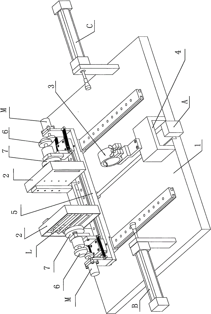
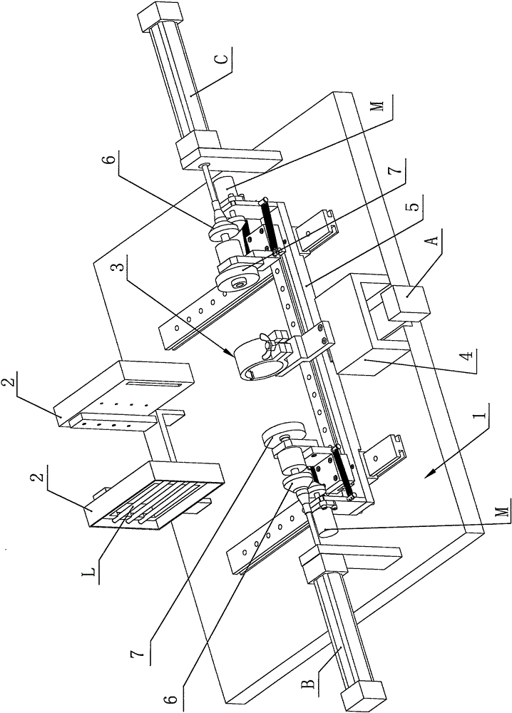
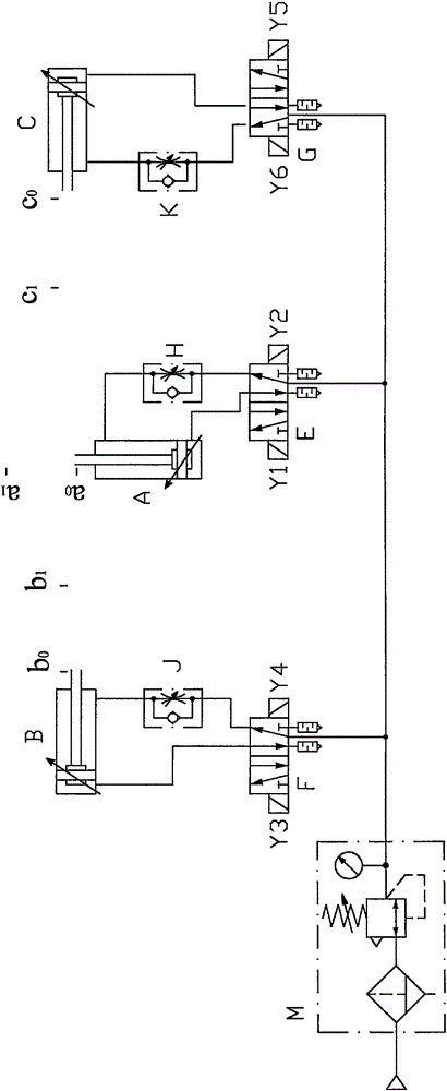
[0023] Such as figure 1 , 2 , 3, and 4, the present invention provides a pneumatic-electric control system of a filter element welding machine, including a pneumatic circuit and a control circuit, and the pneumatic circuit is connected in parallel by a longitudinal branch circuit and two transverse branch circuits Afterwards, the three pneumatic parts M are connected to the same air source to control the actions of the longitudinal drive cylinder A, the transverse drive cylinder B and the transverse drive cylinder C respectively, so as to realize the pneumatic sequential actions of the heating station and welding station of filter element welding. Using the above scheme, before heating, people first put the filter paper tube on the central mesh tube, and install it on the filter paper tube fixture 3, and at the same time, fix the two end covers respectively on the positioning installation discs 7 symmetrically arranged at the two ends of the horizontal direction. Above, the r...


PUM


Abstract

The invention discloses a pneumatic-electronic control system of a filter element welding machine. The pneumatic-electronic control system of the filter element welding machine comprises a pneumatic loop and a control circuit. The pneumatic loop is composed of three branch loops in parallel. Actions of a longitudinal driving cylinder A, a transverse driving cylinder B and a transverse driving cylinder C can be achieved respectively. Each branch loop comprises the corresponding driving cylinder, a two-position five-way reversing valve and a check throttling valve. The two-position five-way reversing valves are connected with the driving cylinders. The check throttling valves are connected to a gas returning path between the driving cylinders and the two-position five-way reversing valves in series. The control circuit is mainly provided with travel switches, a delay relay T1 and a delay relay T2. The travel switches are installed at the stretch-out positions and the retraction positions of piston rods of the driving cylinders A, B and C respectively. The delay relay T1 is used for controlling heating time, and the delay relay T2 is used for controlling welding holding time. Due to the adoption of the scheme, the pneumatic-electronic control sequential action system of the filter element welding machine is provided.

Description

technical field [0001] The invention relates to a filter element welding machine, in particular to a pneumatic-electric control system of the filter element welding machine. Background technique [0002] At present, the most used at home and abroad is the disposable paper filter. The filter element of the filter is composed of a filter paper tube, a central net tube, upper and lower end caps, etc. The cover is glued together, and there are disadvantages such as degumming and short service life. In response to the above-mentioned degumming phenomenon, some manufacturers make the upper and lower end caps with epoxy resin material, pour the epoxy resin into the mold, and naturally solidify with the filter paper cylinder and the central mesh cylinder as a whole. Although the degumming phenomenon has been solved, the production efficiency Low. Also have a part to realize welding by hot plate welding machine, but existing hot plate welding machine also generally has defects such...

Claims


Application Information

Patent Timeline
Patent Type & Authority Applications(China)
IPC IPC(8): F15B21/08F15B13/06B23K37/02B23K37/047B23K37/00
Inventor 陈崇炯张忠远严凌宇何文笔
Owner 溧阳市森德电器有限公司
Why Eureka
Try Eureka