Built-in flushing and cooling valve of hydraulic motor

A hydraulic motor and cooling valve technology, applied in servo motor components, fluid pressure actuating devices, fluid pressure actuating system components, etc., can solve the problems of large hydraulic energy loss, high cost and high oil temperature, and reduce losses , The effect of simplifying installation difficulties, saving energy and environmental protection energy

Inactive Publication Date: 2015-12-23
NINGBO STF HYDRAULIC TRANSMISSIONS CO LTD
View PDF7 Cites 1 Cited by
  • Summary
  • Abstract
  • Description
  • Claims
  • Application Information

AI Technical Summary

Problems solved by technology

[0003] The technical problem to be solved by the present invention is to provide a built-in flushing and cooling valve of the hydraulic motor, which solves the shortcomings of the existing valve circuit design and manufacturing cost, large loss of hydraulic energy and high oil temperature

Method used


Image

  • Built-in flushing and cooling valve of hydraulic motor
  • Built-in flushing and cooling valve of hydraulic motor
  • Built-in flushing and cooling valve of hydraulic motor

Examples


Embodiment 1

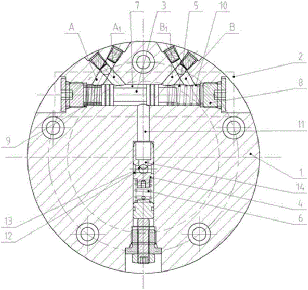
[0021] like figure 1 and 2 As shown, a flushing and cooling valve with a built-in hydraulic motor includes a valve body 1, wherein the valve body 1 includes a two-way variable pump 2, a first valve core 3, a second valve core 4, a first spring 5 and a second valve core. Two springs 6, the two-way variable pump 2 is connected to the oil inlet of the hydraulic motor, the first spool 3 has a cavity 7 in the middle, and the second spool 4 is set at the lower end of the first spool 3 , there is an oil chamber 11 between the first spool 3 and the second spool 4, and the oil chamber 11 communicates with the concave cavity 7, and the second oil hole 13 and the inner oil of the hydraulic motor are arranged in the oil chamber 11 The cavities communicate with each other. A blind hole 14 is provided in the middle of one end of the second spool 4, and the diameter of the blind hole 14 corresponds to the oil chamber 11. The side of the second spool 4 is provided with a first oil hole 12, a...


PUM


Abstract

The invention relates to a built-in flushing and cooling valve of a hydraulic motor. The built-in flushing and cooling valve comprises a valve body. A two-way variable pump, a first valve element, a second valve element, a first spring and a second spring are arranged in the valve body. The two-way variable pump is connected with an oil inlet of the hydraulic motor. A concave cavity is formed in the middle of the first valve element. The second valve element is arranged at the lower end of the first valve element. An oil cavity is formed between the first valve element and the second valve element. The oil cavity is communicated with the concave cavity. A second oil hole is formed in the oil cavity and communicated with an inner oil cavity of the hydraulic motor. A blind hole is formed in the middle of one end of the second valve element. The diameter of the blind hole corresponds to that of the oil cavity. A first oil hole is formed in the side face of the second valve element and communicated with the blind hole. The concave cavity is communicated with the inner oil cavity of the hydraulic motor through the oil cavity, the first oil hole and the second oil hole. A low-pressure oil source in the hydraulic motor can be automatically selected, energy is fully utilized, and the flushing valve can be automatically closed under the special condition; and hydraulic flow in the valve is stable and adjustable, and the valve can be suitable for use working condition integrated forms of different elements and is easy to install.

Description

technical field [0001] The invention belongs to the technical field of hydraulic transmission, in particular to a flushing and cooling valve built in a hydraulic motor. Background technique [0002] In order to improve the working performance and service life of hydraulic components, we usually need to add flushing, cooling and oil replenishment functions to the motor. There are generally two conventional design schemes for hydraulic components plus flushing: 1. Unidirectional rotary motors provide flushing; 2. Bidirectional rotary motors provide flushing. However, both of these two schemes require an oil circuit to be connected to the system circuit, which communicates with the motor casing through a valve, and the manufacturing cost is high. In order for the oil in the circuit to pass through the motor casing, it is usually necessary to connect a low pressure circuit to the circuit. The one-way valve with hydraulic resistance increases the hydraulic energy loss of the sys...

Claims


Application Information

Patent Timeline
Patent Type & Authority Applications(China)
IPC IPC(8): F15B13/02F15B21/00
Inventor 胡品容李成志柴小波董益挺应杰
Owner NINGBO STF HYDRAULIC TRANSMISSIONS CO LTD
Why Eureka
Try Eureka