
Ultrasonic cleaning device

A cleaning device and ultrasonic technology are applied in the directions of cleaning methods and utensils, cleaning methods using liquids, chemical instruments and methods, etc., which can solve the problems of weak cavitation effect, environmental pollution, high labor intensity, etc., and achieve simple and novel structure. Improve cleaning efficiency and enhance the effect of cavitation

Inactive Publication Date: 2015-12-23
无锡博成洋超声设备有限公司
View PDF6 Cites 0 Cited by
  • Summary
  • Abstract
  • Description
  • Claims
  • Application Information

AI Technical Summary

Problems solved by technology

Ultrasound is named for its lower frequency limit greater than the upper limit of human hearing. In the electromechanical industry, there are cleaning requirements from mechanical parts to mechanical parts, from electrical parts to electrical parts, such as gears, crankshafts and even gearboxes, and electrical parts. The assembly of machinery and electrical appliances, as well as some precision mechanical parts and electrical parts, need to be cleaned. Most companies use traditional cleaning methods, such as immersion cleaning and spray cleaning. This cleaning method is not only labor-intensive, but also It is easy to cause environmental pollution and waste of water resources. Some enterprises can use ultrasonic cleaning to eliminate the disadvantages of traditional cleaning in technological transformation, especially for some mechanical parts with complex shapes, which are widely used.
At present, in the existing technology, ultrasonic cleaning uses the cavitation effect of ultrasonic waves in the liquid to vibrate and peel off pollutants such as oily particles on the surface of the cleaning object, so that the dirt layer is dispersed, emulsified, and stirred to achieve the purpose of cleaning. , however, the cavitation effect of ultrasonic cleaning devices currently on the market is relatively weak, and the cleaning ability is poor

Method used


Image

  • Ultrasonic cleaning device

Examples


Embodiment Construction

[0011] The following will clearly and completely describe the technical solutions in the embodiments of the present invention. Obviously, the described embodiments are only some of the embodiments of the present invention, rather than all the embodiments. Based on the embodiments of the present invention, all other embodiments obtained by persons of ordinary skill in the art without making creative efforts belong to the protection scope of the present invention.

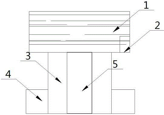
[0012] see figure 1 , the embodiment of the present invention includes:

[0013] An ultrasonic cleaning device, characterized in that it includes: a cleaning tank 1, the cleaning tank 1 is a hollow transparent medium, the inside of the cleaning tank 1 is filled with cleaning liquid, and the inside of the cleaning tank 1 is A heating constant temperature device 2 is provided, and the liquid outlet hole provided under the cleaning tank 1 connects with the horn 3 , and a transducer 4 is provided at one end of the horn ...


PUM


Abstract

The invention discloses an ultrasonic cleaning device which comprises a cleaning tank. The cleaning tank is made of hollow transparent media. Cleaning liquid is contained in the cleaning tank. A heating constant temperature device is arranged in the cleaning tank. A liquid outlet hole is formed in the lower portion of the cleaning tank and is linked with an amplitude transformer. A transducer is arranged at one end of the amplitude transformer. By means of the manner, the ultrasonic cleaning device is simple and novel in structure; it is tested through experiments that cavitation is better facilitated through higher liquid temperature, however, if the temperature is too high, the steam pressure in bubbles is increased, and thus cavitation is weakened due to the fact that the buffering effect is enhanced when the bubbles are closed; thus, the heating constant temperature device additionally arranged in the ultrasonic cleaning device effectively enhances the ultrasonic cavitation effect, enhances the cleaning capability and improves the cleaning efficiency.

Description

technical field [0001] The invention relates to the field of ultrasonic appliances, in particular to an ultrasonic cleaning device. Background technique [0002] Ultrasound is a sound wave with a frequency higher than 20,000 Hz. It has good directionality and strong penetrating ability. It is easy to obtain concentrated sound energy and has a long distance in water. It can be used for distance measurement, speed measurement, cleaning, welding, and stone breaking. , Sterilization, etc., have many applications in medicine, military, industry, and agriculture. Ultrasound is named for its lower frequency limit greater than the upper limit of human hearing. In the electromechanical industry, there are cleaning requirements from mechanical parts to mechanical parts, from electrical parts to electrical parts, such as gears, crankshafts and even gearboxes, and electrical parts. The assembly of machinery and electrical appliances, as well as some precision mechanical parts and elect...

Claims


Application Information

Patent Timeline
IPC IPC(8): B08B3/12B08B3/10
CPCB08B3/12B08B3/10
Inventor 叶乔
Owner 无锡博成洋超声设备有限公司
Learn More