A cyclone reaction device and flue gas desulfurization device

A swirl reaction and flue gas technology, which is applied in the field of desulfurization devices, swirl reaction devices, and flue gas desulfurization devices, can solve the problems of high-pressure pump energy consumption, high maintenance costs, and low flue gas desulfurization efficiency

Active Publication Date: 2017-09-19
龙创信恒(北京)科技有限公司
View PDF4 Cites 0 Cited by
  • Summary
  • Abstract
  • Description
  • Claims
  • Application Information

AI Technical Summary

Problems solved by technology

However, the disadvantages of the current spray desulfurization towers are as follows: firstly, the spray device needs a high-pressure pump to spray out the circulating desulfurization reaction slurry, so a relatively high injection pressure is required, so the energy consumption of the prepared high-pressure pump is relatively high, and it takes a lot of money. A large amount of electric energy causes energy waste; secondly, the nozzles of the spraying device are relatively easy to block, and because the droplets of the sprayed reaction slurry do not have many opportunities to contact the flue gas, and some droplets of the desulfurization reaction slurry do not contact the flue gas at all. It falls without contact, so the flue gas desulfurization efficiency is not high, and the desulfurization effect is not good; in addition, due to the configuration of a relatively multi-layer spray device, the cost is high and the structure is complicated, and additional pulping tanks 511 and sinking tanks 522 are required. Therefore, the overall space occupation is too large and the maintenance cost is relatively high.

Method used


Image

  • A cyclone reaction device and flue gas desulfurization device
  • A cyclone reaction device and flue gas desulfurization device
  • A cyclone reaction device and flue gas desulfurization device

Examples


Embodiment Construction

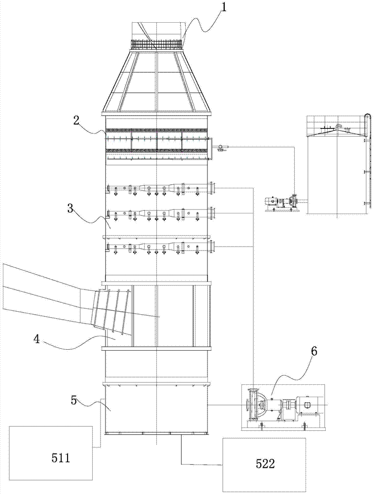
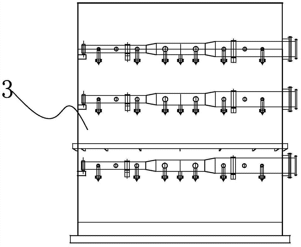
[0041] The following with attached Figure 3 to Figure 11 A cyclone reaction device and a flue gas desulfurization device of the present invention are further described in detail.

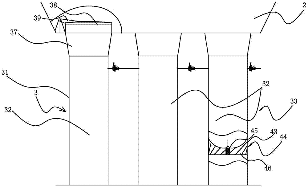
[0042] A kind of cyclone reaction device of the present invention, please refer to Figure 3 to Figure 11, comprising a swirl outer casing 31 and at least two swirl chambers 32 horizontally arranged in the swirl outer casing 31, at least one swirler 33 horizontally arranged in the swirl chamber 32, the swirl chamber 32 is provided with a circulating reaction slurry inlet 34, the swirl chamber 32 is communicated with the gas homogenizer 4 below, the swirl 33 includes a swirl impeller 44 arranged horizontally, and the swirl impeller 44 includes a The impeller casing 43, the impeller central shaft 45 arranged in the center and at least five spirally rising swirl blades 46, the swirl blades 46 are arranged around the impeller central shaft 45, the impeller casing 43 is fixed on the swirl In the chamb...


PUM


Abstract

The invention discloses a swirl reaction device and a flue gas desulfurization device, wherein the swirl reaction device includes a swirl outer casing and at least two swirl chambers provided with at least one swirl device, and the upper part of the swirl chamber is provided with a circulating reaction slurry inlet , the bottom of the swirl chamber communicates with the air equalization chamber, the swirl is a swirl impeller including the impeller casing, the central shaft of the impeller and at least five swirl blades, the swirl blades are arranged around the central shaft of the impeller, and the impeller casing is fixed in the swirl chamber , the inner edge of the swirl blade is fixed to the central axis of the impeller, the outer edge of the swirl blade is fixed to the impeller casing, and at least one swirl chamber top is provided with a flue gas flow adjustment device that can open and close the swirl chamber, the flue gas flow adjustment device Connect to the top of the swirl chamber. The swirl reaction device of the present invention has a simple structure, and the number of swirl chambers participating in the reaction can be selected to effectively control the flue gas flow rate, ensure the flue gas desulfurization effect and desulfurization rate, save energy and avoid environmental pollution.

Description

technical field [0001] The invention relates to a reaction device used in desulfurization, in particular to a cyclone reaction device. [0002] The present invention also relates to a desulfurization device, in particular to a flue gas desulfurization device comprising the aforementioned cyclone reaction device. Background technique [0003] With the continuous development of social industry, the degree of industrialization is getting higher and higher, the scale of production is expanding, and more and more flue gas is discharged into the atmosphere. Among the various gaseous pollutants that affect air quality, SO 2 The flue gas has the largest quantity and the greatest impact. It causes acid rain, destroys the ecological environment, and affects people's health. Therefore, before these industrial flue gases are discharged into the atmosphere, they all need to be treated, and the most important one is desulfurization treatment. [0004] Currently, if figure 1 and figur...

Claims


Application Information

Patent Timeline
Patent Type & Authority Patents(China)
IPC IPC(8): B01D53/80B01D53/75B01D53/83B01D53/50
Inventor 刘志伟徐霄龙高向武焦烨鋆
Owner 龙创信恒(北京)科技有限公司
Why Eureka
Try Eureka