Hydraulic braking system

A braking system, braking device technology, applied in elevators, transportation and packaging, etc., can solve the problems of high energy demand, high energy consumption, expensive use of accumulators and regulating valves, etc.

Active Publication Date: 2015-12-16
INVENTIO AG
View PDF10 Cites 3 Cited by
  • Summary
  • Abstract
  • Description
  • Claims
  • Application Information

AI Technical Summary

Problems solved by technology

[0004] The braking safety device known from EP0648703A1 for an elevator car has the disadvantage that the operation of the braking device and the adjustment of the braking force are complicated
Especially the use of pressure accumulators and regulating valves is expensive and complicated
For reliable regulating operation, it is also necessary to regulate and maintain the pressure in the pressure accumulator within the narrowest possible pressure range, which requires frequent switching on and off of motors and pumps as well as precise operation of the switching elements and Correspondingly frequent maintenance work
In addition, in the type of operation in which the brake is closed by means of pressure in the pressure accumulator, the hydraulic system needs to use components that are as leak-free as possible, since otherwise it is used for regular subsequent replenishment of pressure medium or for maintaining the brake pressure for economical operation Excessive energy consumption
However, in the type of operation in which the brake pressure is reduced by means of the pressure of the pressure medium device, the problem arises that the pressure of the pressure medium device must be continuously maintained in order to ensure operational readiness, which creates a high energy demand
Especially due to the large number of components or elements required in hydraulic systems, leakage losses occur, with correspondingly high energy consumption and high maintenance requirements

Method used


Image

  • Hydraulic braking system
  • Hydraulic braking system
  • Hydraulic braking system

Examples


Embodiment Construction

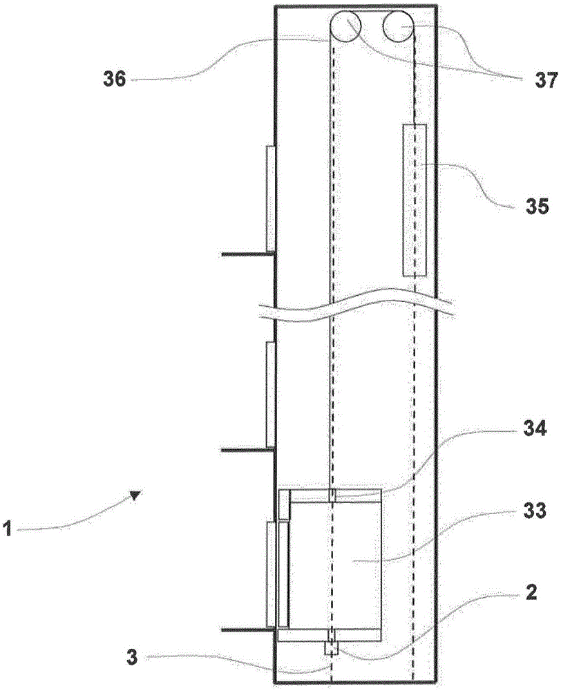
[0033] figure 1 A people transport system 1 is shown with a brake system 2 , which is designed as an elevator (lift system) 1 . In a correspondingly modified embodiment, the people transport device 1 can also be designed as an escalator or a moving walkway.

[0034] The people conveyor 1 has an elevator car 33 . The elevator car 33 is suitable for accommodating people or goods. The elevator car 33 is connected in the example to a counterweight 35 by means of a carrier mechanism 36 via a drive 37 . The elevator car 33 is guided on the guide rail 3 by means of guide shoes 34 . The guide rail 3 comprises a rail seat and a guiding and braking web 4 . The rail mounts of the guide rails 3 can be connected, for example, in the elevator shaft of the elevator 1 to a wall of the elevator shaft or to a suitable support structure. In this case, the braking system 2 corresponds to the braking web 4 of the guide rail 3 . In general, a pair of guide rails 3 is used in such a people con...


PUM


Abstract

A braking system (2) is used for a passenger transport installation (1) in the form of a lift, escalator or moving walkway. The braking device (5) comprising actuation equipment (7) is provided in this respect. Also provided are a pump (16) supplying a brake fluid to the piston space (11) of the actuation equipment (7) and a motor (15) which drives the pump (16). According to the invention, a control device (14) is also provided, which controls the motor (15) by way of a frequency inverter (19) in such a manner that the pump (16) supplies brake fluid at a delivery flow rate (QP) predetermined by the control device (14). A return flow rate (QL) is also made possible, wherein the pressure (pB) is set in the piston space (11) of the actuation equipment (7) corresponding to an equilibrium in which the delivery flow rate (Qp) is equal to the return flow rate (QL). The control device (14) sets the pressure (pB) in the piston space (11) of the actuation equipment (7) by way of the delivery flow rate (QP) of the pump (16). The invention also relates to a passenger transport installation (1) in the form of a lift, escalator or moving walkway having a braking system of this kind and to a method for controlling the braking force in a passenger transport installation (1) of this kind.

Description

technical field [0001] The invention relates to a braking system for a people conveyor designed as an elevator, rolling ladder or moving walkway; a corresponding people conveyor; and a method for controlling the braking force in such a people conveyor . The invention relates in particular to the field of lift installations. Background technique [0002] A brake safety device for an elevator car is known from EP0648703A1. In this case, a braking device engaging on the guide rail is provided, wherein the braking force exerted by the braking device on the guide rail is adjusted by the adjusting device. The braking device surrounds the free arm of the guide rail which is provided with the running rails, wherein for each running rail a respective brake plate is provided which is carried by the brake plate holder. Furthermore, at least one of the brake plates can be actuated by means of a brake cylinder, wherein the brake cylinder can be acted upon by a pressure generated in th...

Claims


Application Information

Patent Timeline
Patent Type & Authority Applications(China)
IPC IPC(8): B66B5/18
CPCB66B5/18
Inventor 雷托·楚佩尔特
Owner INVENTIO AG
Why Eureka
Try Eureka