
Display

A display and display device technology, applied in instruments, optical components, optics, etc., can solve problems such as reducing the user's viewing experience, reducing the adjustment effect of the human eye, and blurring images.

Active Publication Date: 2015-12-16
BEIJING G WEARABLES INFORMATION SCI & TECH
View PDF5 Cites 5 Cited by
  • Summary
  • Abstract
  • Description
  • Claims
  • Application Information

AI Technical Summary

Problems solved by technology

[0002] The image formed by the existing display generally diverges everywhere, and the user can watch the image formed by the display at different angles. When viewing, the user needs to adjust the human eyes to clearly view the image formed by the display. Therefore, long-term adjustment will cause visual fatigue of the human eye
[0003] The existing near-eye display (head-mounted display), whether it is a VR (Virtual Reality, virtual reality) display or an AR (Augmented Reality, augmented reality) display, can focus the image on the retina of the human eye through a set of lenses. In this way, the adjustment function of the human eye will be reduced to a certain extent, and the visual fatigue of the human eye will be reduced. However, the image generated in this case is a virtual image, and the human eye will adjust the focus according to the position of the virtual image. The actual position of the image is on the screen, so the image cannot be seen clearly after the focus is adjusted. At this time, the human eye needs to adjust the focus again. Repeated adjustments like this will also cause visual fatigue and reduce the user's viewing experience

Method used


Image

  • Display
  • Display
  • Display

Examples


Embodiment Construction

[0044] Preferred embodiments of the present disclosure will be described in more detail below with reference to the accompanying drawings. Although preferred embodiments of the present disclosure are shown in the drawings, it should be understood that the present disclosure may be embodied in various forms and should not be limited to the embodiments set forth herein. Rather, these embodiments are provided so that this disclosure will be thorough and complete, and will fully convey the scope of the disclosure to those skilled in the art.

[0045] Firstly, the invention principle of the display of the present invention is briefly described.

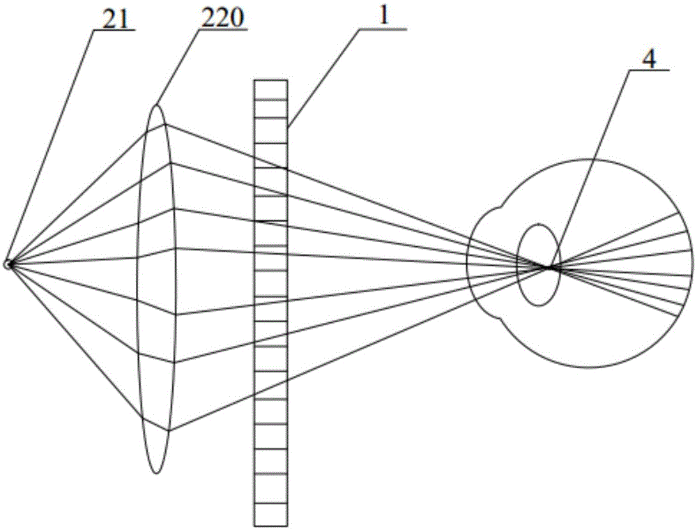
[0046] In the optical system, the nodal point is a pair of conjugate points with angular magnification = +1. The light pointing to the object space node is refracted by the optical system, which is equivalent to being emitted from the image space node without changing the relationship with the optical axis. angle. The node of the human e...


PUM


Abstract

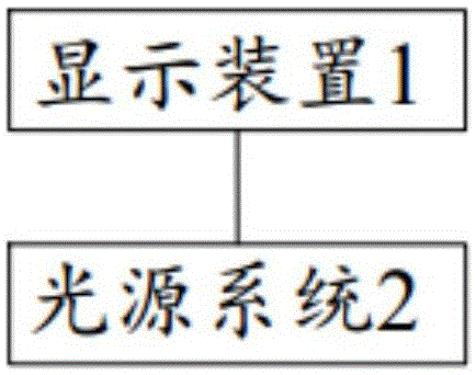
The invention discloses a display which comprises a display device and a light source system. The display device comprises multiple pixels, and the transmittivity or reflectivity of each pixel can be adjusted; the light source system is used for projecting light onto the display device and designed to be capable of enabling emergent light of the pixels of the display device to point to a predetermined convergence point in the space. Accordingly, when the display is used, the position of the convergence point of illumination light can be adjusted according to the position of a human eye node, so that the convergence point can coincide with the human eye node; in this way, a user can receive image information on the display without deviation without needing human eye adjustment.

Description

technical field [0001] The present invention relates to a display device, in particular to a display. Background technique [0002] The image formed by the existing display generally diverges everywhere, and the user can watch the image formed by the display at different angles. When viewing, the user needs to adjust the human eyes to clearly view the image formed by the display. Therefore, adjusting for a long time will cause visual fatigue of the human eye. [0003] The existing near-eye display (head-mounted display), whether it is a VR (Virtual Reality, virtual reality) display or an AR (Augmented Reality, augmented reality) display, can focus the image on the retina of the human eye through a set of lenses. In this way, the adjustment function of the human eye will be reduced to a certain extent, and the visual fatigue of the human eye will be reduced. However, the image generated in this case is a virtual image, and the human eye will adjust the focus according to the...

Claims


Application Information

Patent Timeline
IPC IPC(8): G02B27/01G02B27/22
CPCG02B27/0172G02B30/27
Inventor 肖真郭成
Owner BEIJING G WEARABLES INFORMATION SCI & TECH
Learn More