
Loop difference testing apparatus of transformer substation direct-current power supply system

A technology of a DC power supply system and a testing device, which is applied in the field of power supply equipment, can solve the problems of inability to cooperate with different levels, potential safety hazards in the field of power transmission and transformation, and inability to test, and achieves the effects of convenient testing, light weight, and prevention of leapfrog misoperation.

Inactive Publication Date: 2015-12-16
STATE GRID CORP OF CHINA +2
View PDF9 Cites 1 Cited by
  • Summary
  • Abstract
  • Description
  • Claims
  • Application Information

AI Technical Summary

Problems solved by technology

Based on the internal resistance of the transmission feeder of the DC power supply circuit of the substation, and the protection components are different, its operating characteristics can only be distinguished from different currents, and it is completely impossible to actually correct the problem of differential coordination.
Although the existing circuit breakers have been tested for action tripping when they leave the factory, in the actual composition of the feeder, the leapfrog action may be caused by different internal resistances, different varieties, different batches, and different operating times.
Potential safety hazards have been brought to the field of power transmission and transformation
Electric workers have been promoting circuit breakers with fuse characteristics as a purpose to solve the possibility of skipping the trip, because it is impossible to test and it is impossible to accurately judge whether there is a possibility of skipping the action of the DC power supply circuit

Method used


Image

  • Loop difference testing apparatus of transformer substation direct-current power supply system

Examples


Embodiment Construction

[0013] The present invention will be described in further detail below in conjunction with the accompanying drawings.

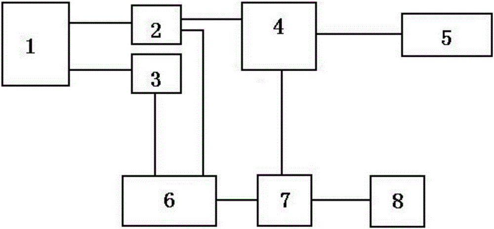
[0014] like figure 1 As shown, the substation DC power system loop level difference test device includes: DC load interface 1, current sampling circuit 2, voltage sampling circuit 3, grid-connected inverter device 4, access grid unit 5, A / D converter 6 , a computer 7 and a report output unit 8; its circuit connection is that the DC output interface 1 is connected with the current sampling circuit 2 and the voltage sampling circuit 3 respectively; the current sampling circuit 2 is connected with the grid-connected inverter device 4 and the A / D converter respectively 6 are connected; the voltage sampling circuit 3 is connected with the A / D converter 6; the grid-connected inverter device 4 is respectively connected with the grid unit 5 and the computer 7; the A / D converter 6 is connected with the computer 7; the computer 7 is connected with the report The outpu...


PUM


Abstract

The invention, which belongs to the technical field of the power supply equipment, provides a loop difference testing apparatus of a transformer substation direct-current power supply system. In order to solve problems existing in the prior art, the testing apparatus is characterized in that a direct-current output interface is connected with a direct-current fuse load terminal at a final stage and sends a current to a grid-connected inverter based on sampling of a current sampling circuit and a voltage sampling circuit. The grid-connected inverter converts the direct current into a grid-connected alternating current and transmits the current to an access grid unit; and the access grid unit transmits an alternating-current signal to the power grid back. The grid-connected inverter uses a computer to control and adjust different current outputs, thereby generating currents from 0 to 500A to enable a protection element of the direct-current power loop to make action. The current sampling circuit and the voltage sampling circuit can carry out sampling on a current value and a voltage value during the motion of a circuit breaker; signals are transmitted to an A / D converter simultaneously; the A / D converter converts analog signals into digital signals that are transmitted to the computer; the computer calculates the digital signals and determines the motion characteristic of the direct-current loop according to different currents and motion time; and then the computer inputs the signals into a report output unit by a report conversion tool.

Description

technical field [0001] The invention relates to a test and calibration device for electric power transformation equipment, in particular to a test device for level difference matching of a power supply circuit of a DC power supply system of a substation, and belongs to the technical field of electric power supply equipment. Background technique [0002] Substation DC power supply system is designed to provide working power for computer equipment, control equipment, protection equipment, automation equipment, telecontrol equipment, and communication equipment. Due to the importance of the equipment, the purpose of using a DC power supply is to achieve uninterrupted power supply and long-term stable power supply of the equipment. The purpose of adopting multi-level protection is to control the fault to the minimum range when the faults such as overload and short circuit of the DC power supply circuit occur, and will not affect the normal operation of the equipment. Each circu...

Claims


Application Information

Patent Timeline
IPC IPC(8): G01R31/40
Inventor 陈洪涛赵建明张海明孟祥辰项福军张晶玉赵强田雨洁
Owner STATE GRID CORP OF CHINA
Learn More