Device and method for suppressing mechanical coupling error of dual-mass silicon microgyroscope

A technology of silicon micro gyroscope and coupling error, which is applied in the field of MEMS and micro inertial measurement, can solve the problems of structural torsion, silicon micro gyroscope performance degradation, follow-up, etc., to reduce the rotation effect, reduce the follow-up effect, reduce effect of influence

Active Publication Date: 2018-02-06
SOUTHEAST UNIV
View PDF5 Cites 0 Cited by
  • Summary
  • Abstract
  • Description
  • Claims
  • Application Information

AI Technical Summary

Problems solved by technology

The fully decoupled structure is the most thorough decoupling in form, but due to some structural design defects, there is still a certain coupling effect between the two, and it may also produce some structural torsion, follow-up and other effects, so that degrades the performance of silicon microgyroscopes

Method used


Image

  • Device and method for suppressing mechanical coupling error of dual-mass silicon microgyroscope
  • Device and method for suppressing mechanical coupling error of dual-mass silicon microgyroscope
  • Device and method for suppressing mechanical coupling error of dual-mass silicon microgyroscope

Examples


Embodiment Construction

[0021] The present invention will be further described below in conjunction with the accompanying drawings.

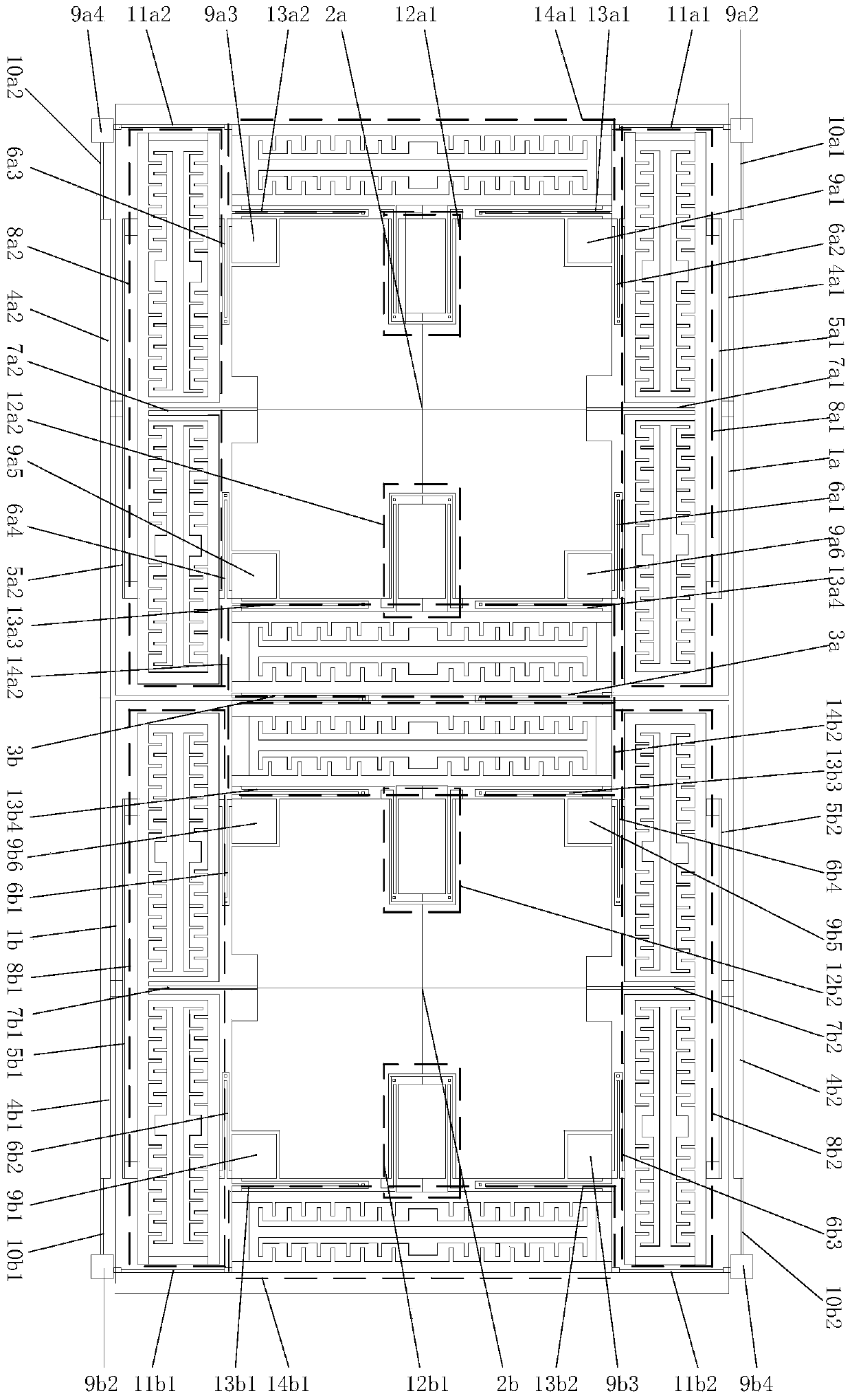
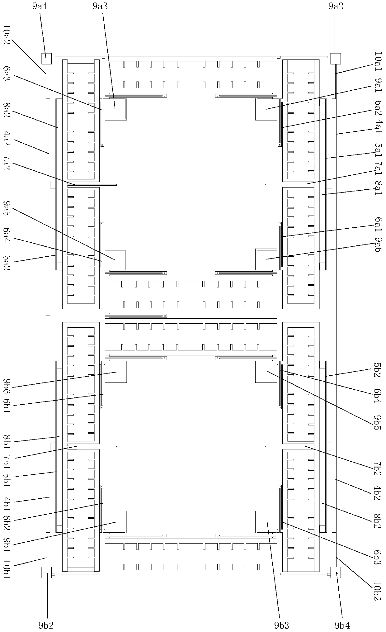
[0022] combined with figure 1 , the mechanical coupling error suppression method and device of the double-mass silicon micro-gyroscope of the present invention realize the measurement of the input angular velocity perpendicular to the x-y horizontal plane. The structure is divided into upper and lower layers, the upper layer is the vibrating mechanical structure of the silicon micro gyroscope, and the lower layer is the glass substrate adhered with signal leads. The mechanical structure of the gyroscope is composed of two symmetrically placed identical single-mass angular velocity measurement unit substructures 1a and 1b; in the driving mode, the two single-mass angular velocity measurement unit substructures are driven by coupling folded beams 3a and 3b Establish association, in the detection mode, establish association through beams 4a1, 4b1, 4a2, 4b2, beams 4a1, 4b...


PUM


Abstract

The invention discloses a device and method for inhibiting a mechanical coupling error of a dual-mass silicon microgyroscope. The device comprises an upper layer and a lower layer, wherein the upper layer is a mechanical structure of the microgyroscope and the lower layer is a glass substrate adhered to a signal leading wire. The mechanical structure of the microgyroscope is composed of two identical sub-structures, which are symmetrically arranged on the left side and the right side separately. The two sub-structures are connected through a driven coupling folded beam and cross beam, so that the two sub-structures are related to each other at both of a driven mode and a detection mode. Through adopting a single beam in a driven decoupling beam, and adjusting the stiffness ratio of an under beam of the cross beam to a detected folded beam, a rotational effect and a mechanical coupling error of a detection mechanism are eliminated in structural design. The length of the cross beam of a pedestal and a position of an anchor point are adjusted to enable the detection mechanism to linearly move in the detection mode. A balancing stabilizing beam is adopted, and the stiffness ratio of the balancing stabilizing beam to the driven coupling folded beam is set, so that movement status of left and right driving mechanisms of a mass block is kept consistent.

Description

technical field [0001] The invention belongs to MEMS (Micro-Electro-Mechanical System) and micro-inertial measurement technology, in particular to a mechanical coupling error suppression device and method for a double-mass silicon micro-gyroscope. Background technique [0002] In the mid-1980s, with the advancement of semiconductor processing technology, the miniaturization and integration of mechanical structures and electronic systems—the emergence of micro-electromechanical systems (MEMS) technology brought a revolution to the field of inertial sensors. Since Draper's laboratory first demonstrated its silicon microgyroscope in 1991, silicon microgyroscopes based on surface processing, bulk silicon processing or a hybrid processing technology of the two have emerged continuously. Micromechanical gyroscopes have broad application prospects and military application value due to their miniaturization and integration, high reliability, low power consumption, easy digitization ...

Claims


Application Information

Patent Timeline
Patent Type & Authority Patents(China)
IPC IPC(8): G01C25/00
CPCG01C25/005
Inventor 杨波邓允朋王行军胡迪吴磊
Owner SOUTHEAST UNIV
Why Eureka
Try Eureka