
Rubber tube mark printing system based on computer control

A computer and rubber tube technology, applied to the general parts of printing machinery, printing, printing machines, etc., can solve the problems of pigments mixing with each other, achieve the effects of reducing heating, increasing service life, and ensuring the printing effect

Active Publication Date: 2021-09-28
HENAN IND & TRADE VOCATIONAL COLLEGE
View PDF17 Cites 0 Cited by
  • Summary
  • Abstract
  • Description
  • Claims
  • Application Information

AI Technical Summary

Problems solved by technology

[0005] The purpose of the present invention is to overcome the deficiencies in the prior art, solve or at least alleviate the problem that the pigments are easily mixed with each other when the rubber hose logo is printed multiple times, and provide a computer-based rubber hose marking system

Method used


Image

  • Rubber tube mark printing system based on computer control
  • Rubber tube mark printing system based on computer control
  • Rubber tube mark printing system based on computer control

Examples


Embodiment 1

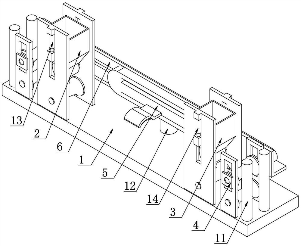
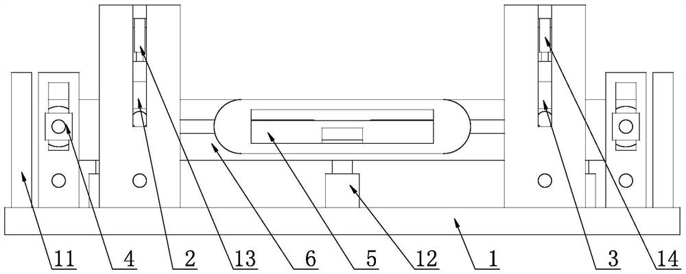
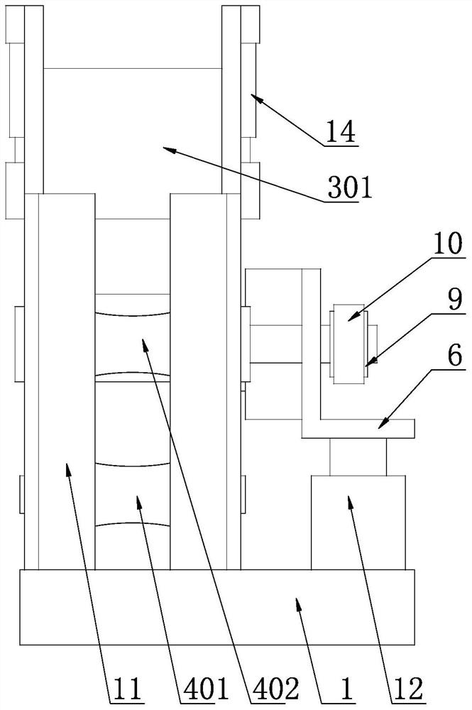
[0046] Such as Figure 1-13 As shown, a rubber hose marking system based on computer control, the rubber hose marking system includes a base 1, and the upper part of the base 1 is sequentially provided with a marking assembly 2 and a coating assembly 3 according to the conveying direction of the rubber hose. The rubber hose marking system also includes a positioning drive Component 4 and paint drying component 5, two sets of positioning drive components 4 are respectively located at the front end of the marking component 2 and the rear end of the coating component 3, and the pigment drying component 5 is located between the marking component 2 and the coating component 3;

[0047] The positioning drive assembly 4 includes a first idler roller 401 and a positioning roller 402. The first idler roller 401 is installed on the base 1 for lateral rotation, and the positioning roller 402 is located above the first idler roller 401. The positioning roller 402 is installed on the base 1...


PUM


Abstract

The invention relates to a rubber tube mark printing system based on computer control. The rubber tube mark printing system comprises a base, the upper part of the base is sequentially provided with a mark printing assembly and a coating assembly according to the conveying direction of a rubber tube, the rubber tube mark printing system further comprises positioning driving assemblies and a pigment drying assembly, the two positioning driving assemblies are located at the front end of the mark printing assembly and the rear end of the coating assembly correspondingly, and the pigment drying assembly is located between the mark printing assembly and the coating assembly. The rubber tube mark printing system aims to solve or at least alleviate the problem that pigments are easily mixed when a rubber tube mark is printed for multiple times, and the rubber tube mark printing system based on computer control is provided.

Description

technical field [0001] The invention relates to the technical field of computer control, in particular to a rubber hose marking system based on computer control. Background technique [0002] Hydraulic hose alias hydraulic oil hose, hydraulic hose, high pressure hose, hydraulic hose, steel wire high pressure hose, steel wire braided hose, steel wire wound hose, generally divided into steel wire braided hydraulic hose and steel wire wound hydraulic hose, hydraulic hose structure: mainly composed of liquid-resistant synthetic Rubber inner rubber layer, middle rubber layer, multi-layer reinforced layer, and weather-resistant synthetic rubber outer rubber layer. The inner rubber layer has the function of making the conveying medium withstand pressure and protecting the steel wire or wire fiber from erosion. The outer rubber layer protects and strengthens The layer is not damaged, and the reinforcing layer is a skeleton material, which is used to ensure the pressure of the hose. ...

Claims


Application Information

Patent Timeline
Patent Type & Authority Applications(China)
IPC IPC(8): B41F33/00
CPCB41F17/10B41F23/04B41F21/00
Inventor 李彩霞甄华邱俊玲
Owner HENAN IND & TRADE VOCATIONAL COLLEGE
Learn More