UAV-based missile attack route planning method
A technology for route planning and unmanned aerial vehicles, which is applied to self-propelled missiles, offensive equipment, projectiles, etc., and can solve problems such as attack failure, difficulty in tracking and locking targets with optoelectronic payloads, and loss of optoelectronic payloads.
- Summary
- Abstract
- Description
- Claims
- Application Information
AI Technical Summary
Problems solved by technology
Method used
Image
Examples
Embodiment 1
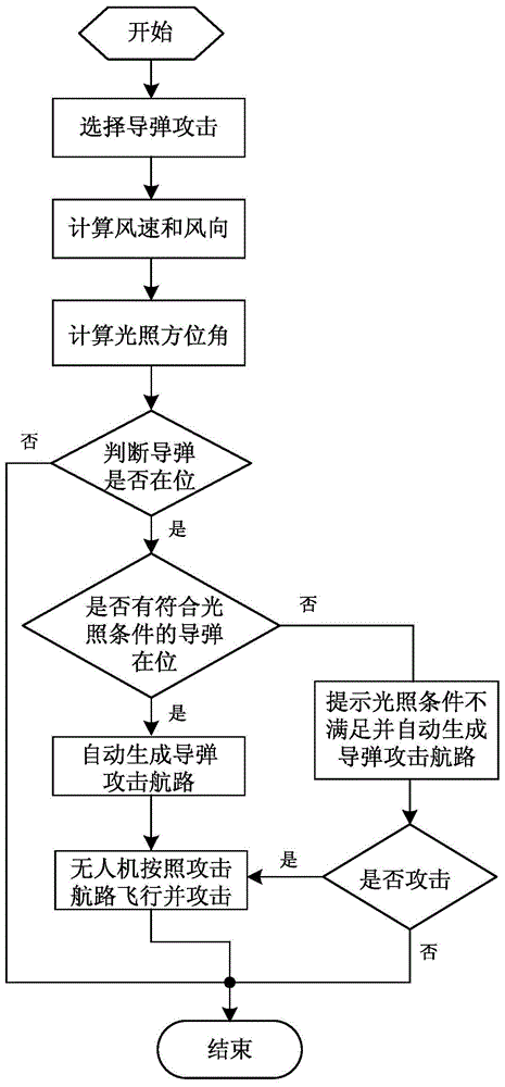
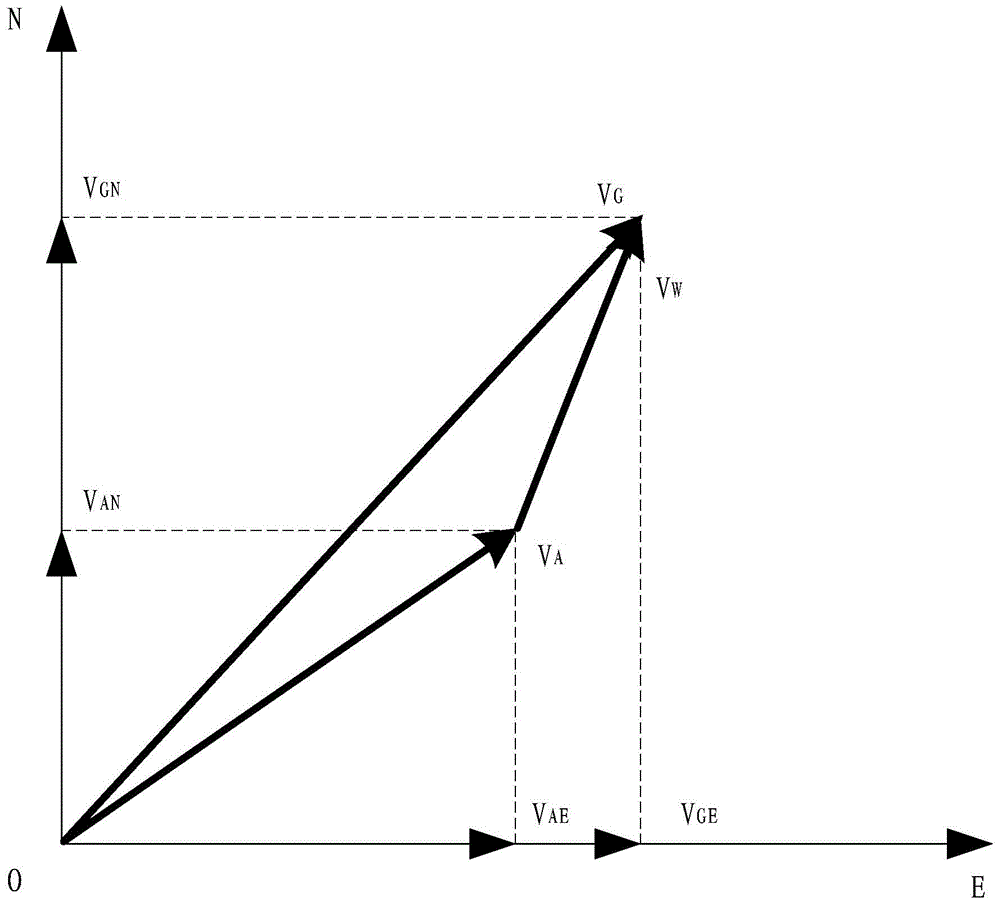
[0081] Step 1. When the UAV is flying at a predetermined altitude, according to the flight parameters of the UAV, including the flight height H, heading angle ψ, and track angle , flight ground speed|V G | and indicated airspeed |V A' |, the calculated wind speed in the flying airspace of the UAV is 4m / s and the wind direction is 130°. Clock hand rotation; and determining the azimuth S of the sun's illumination according to local time W is 60°, and the azimuth angle of sunlight is the angle of the incident direction of the sun's rays, taking the true north as 0°, the range is 0° to 360°, and it rotates clockwise.
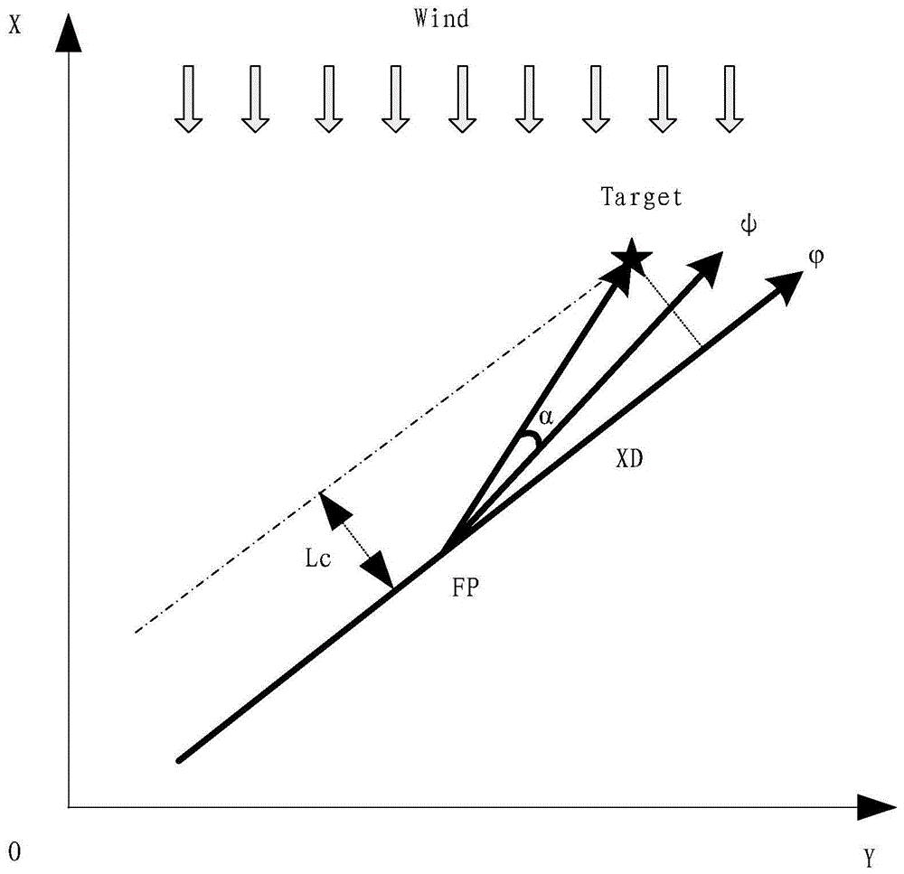
[0082] Step 2. According to the wind speed and wind direction obtained in Step 1, calculate the track angles of the UAVs attacked by the left and right missiles, specifically: when the wind speed |V W | is 4m / s, less than the preset positive lateral wind speed V C When the upper limit of 10m / s, then make the wind direction δ perpendicular to the ground speed di...
Embodiment 2
[0086] Step 1. When the UAV is flying at a predetermined altitude, according to the flight parameters of the UAV, including the flight height H, heading angle ψ, and track angle , flight ground speed|V G | and indicated airspeed |V A' |, calculate the wind speed and wind direction of 8m / s and 70° in the flying airspace of the UAV; and determine the azimuth S of the sun illumination according to the local time W is 335°.
[0087] Step 2. According to the wind speed and wind direction obtained in Step 1, calculate the track angles of the UAVs attacked by the left and right missiles, specifically: when the wind speed |V W | is 8m / s, less than the preset positive lateral wind speed V C When the upper limit of 10m / s, then make the wind direction δ perpendicular to the ground speed direction of the UAV, and then determine the track angle of the UAV . The track angle of the missile attack route on the right side is 340 °, and the track angle of the missile attack route on the ...
Embodiment 3
[0091] Step 1. When the UAV is flying at a predetermined altitude, according to the flight parameters of the UAV, including the flight height H, heading angle ψ, and track angle , flight ground speed|V G | and indicated airspeed |V A' |, calculate the wind speed and wind direction of 15m / s and 220° in the flying airspace of the UAV; and determine the azimuth S of the sun illumination according to the local time W is 30°.
[0092] Step 2. According to the wind speed and wind direction obtained in Step 1, calculate the track angles of the UAVs attacked by the left and right missiles, specifically: when the wind speed |V W |is 15m / s, greater than the preset positive lateral wind speed V C When the upper limit of 10m / s, the wind speed is decomposed so that one of the components is equal to the preset positive lateral wind speed V C , and the wind direction of this component is perpendicular to the ground speed direction of the UAV, so as to determine the track angle of the UA...
PUM
 Abstract
Description
Claims
Application Information
 - R&D Engineer
- R&D Manager
- IP Professional
- Industry Leading Data Capabilities
- Powerful AI technology
- Patent DNA Extraction
Browse by: Latest US Patents, China's latest patents, Technical Efficacy Thesaurus, Application Domain, Technology Topic, Popular Technical Reports.
© 2024 PatSnap. All rights reserved.Legal|Privacy policy|Modern Slavery Act Transparency Statement|Sitemap|About US| Contact US: help@patsnap.com


