Eureka AIR delivers breakthrough ideas for toughest innovation challenges, trusted by R&D personnel around the world.

Fountain type chilled water storage system for large place

A water cooling and fountain-type technology, applied in the field of energy storage, can solve the problems of single structure and appearance of the air-conditioning system, achieve beautiful visual effects, increase consumption desire, and spectacular visual effects

Inactive Publication Date: 2015-12-16
许文辉
View PDF8 Cites 0 Cited by
  • Summary
  • Abstract
  • Description
  • Claims
  • Application Information

AI Technical Summary

Problems solved by technology

[0006] The purpose of the present invention is to solve the above-mentioned problems in the prior art, and provide a fountain-type water storage system for large-scale places, which has beautiful visual effects and high cooling efficiency when used in large-scale places , to solve the problems of single structure and appearance of the air conditioning system in the existing large places

Method used


Image

  • Fountain type chilled water storage system for large place
  • Fountain type chilled water storage system for large place

Examples


Embodiment Construction

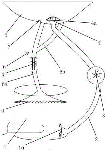
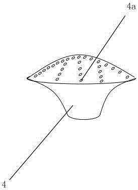
[0026] Such as figure 1 and figure 2 As shown, the fountain-type water cold storage system used in large-scale places includes a cylindrical cold storage tank 1. The outer wall of the cold storage tank 1 is covered with a layer of insulation layer. The cold storage tank 1 has refrigeration pipes. From top to bottom, it is divided into a hot water layer, a thermocline layer and a cold water layer. The cold water layer is connected with a water outlet pipe 2, and a water pump 3 is provided on the water outlet pipe 2. There is a cone-shaped spray head 4 with multiple spray holes 4a. The water cooling system also includes a spray pool 5. The bottom of the spray pool 5 is arc-shaped. The cold storage pool 1 is located underground, and the spray pool 5 is located on the ground. , the nozzle 4 protrudes from the bottom of the fountain 5, the hot water layer is connected with a water inlet pipe 6, the inner end of the water inlet pipe 6 is connected with the cold storage pool 1, the...


PUM


Abstract

The invention provides a fountain type chilled water storage system for a large place and belongs to the field of energy storage. The chilled water storage system comprises a cylindrical cold energy storage tank. A heat insulation layer wraps the outer wall of the cold energy storage tank. The cold energy storage tank is internally provided with a refrigerating pipe. The interior of the cold energy storage tank is divided into a hot water layer, a thermocline layer and a cold water layer from top to bottom according to water temperatures. The cold water layer is communicated with a water outlet pipe. The water outlet pipe is provided with a water pump. The inner end of the water outlet pipe is communicated with the cold energy storage tank. The outer end of the water outlet pipe is connected with a conical spray head. The spray head is provided with a plurality of spray holes. The chilled water storage system further comprises a spray pond. The bottom of the spray pond is in a circular arc shape. The cold energy storage tank is located underground. The spray pond is located on the ground. The spray head extends out of the bottom of the spray pond. The hot water layer is communicated with a water inlet pipe. The inner end of the water inlet pipe is communicated with the cold energy storage tank. The outer end of the water inlet pipe is communicated with the bottom of the spray pond. The bottom wall of the spray pond is provided with a pressure sensor. The water inlet pipe is provided with a solenoid valve. The pressure sensor controls the solenoid valve. The chilled water storage system is attractive in appearance and high in refrigerating efficiency in the using process.

Description

technical field [0001] The invention belongs to the field of energy storage and relates to a fountain type water cold storage system used in large places. Background technique [0002] Water storage technology uses the difference in peak and valley electricity prices to store cooling capacity in water during low electricity price periods, and use stored low-temperature frozen water to provide cooling for air conditioners during peak hours of electricity consumption during the day. When the use time of the air conditioner is synchronized with the use time of the non-air conditioner and the peak and trough of the power grid, the power consumption of the air conditioner in the peak time of the power grid can be transferred to the trough of the power grid to save electricity. The most mature and effective cold storage method currently used is natural stratification. [0003] Natural stratification is temperature stratification. Temperature stratified water storage uses the phys...

Claims


Application Information

Patent Timeline
Patent Type & Authority Applications(China)
IPC IPC(8): F24F5/00F24F11/02
CPCF24F5/0017F24F11/30F24F11/83F24F11/84F24F11/89F24F2005/0032F24F2110/00F24F2140/12Y02E60/14
Inventor 许文辉杨宇楠
Owner 许文辉
Why Eureka
Eureka Blog
Learn More