Locking and pressurizing bone setting device

A bone plate and compression hole technology, applied in the direction of fixator, internal fixator, internal bone synthesis, etc., can solve the problems of too many screws, large damage to the patient's soft tissue and bone tissue, and increase the patient's bone nonunion. Small volume, recovery of limb function, and reliable internal fixation

Inactive Publication Date: 2015-12-16
谢文平
View PDF11 Cites 2 Cited by
  • Summary
  • Abstract
  • Description
  • Claims
  • Application Information

AI Technical Summary

Problems solved by technology

However, this method uses too many screws, which causes too much damage to the patient's soft tissue and bone tissue, and further increases the possibility of bone nonunion in the patient.

Method used


Image

  • Locking and pressurizing bone setting device
  • Locking and pressurizing bone setting device
  • Locking and pressurizing bone setting device

Examples


Embodiment 1

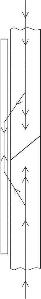
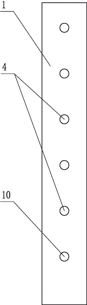
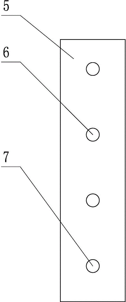
[0029] Depend on figure 2 , image 3 , Figure 4 , Figure 5 It can be known that a locking and compression bone setting device includes a main locking and compression bone setting plate 1, a locking screw 2, and a sleeve 9. The main locking and compression bone setting plate 1 is provided with a main locking screw hole 4 corresponding to the locking screw 2, It also includes an auxiliary locking bone plate 5 and two positioning rods 8 corresponding to the sleeve 9. The auxiliary locking bone plate 5 is applied simultaneously with the main locking compression bone plate 1, and at least one of the auxiliary locking bone plates 5 is provided. Secondary locking screw hole 7 and one secondary screw hole 6, the position and size of the secondary locking screw hole 7 and secondary screw hole 6 are corresponding to the main locking screw hole 4. During application, the secondary locking screw hole 7 and secondary screw hole The holes 6 are respectively distributed on both sides o...

Embodiment 2

[0037] Depend on Figure 9 , Figure 10 , Figure 11It can be seen that in this embodiment, the main locking and compression bone plate 1 is provided with 8 main locking screw holes 4, one of which is a pressure hole 10, and the auxiliary locking bone plate 5 is provided with 3 auxiliary screw holes 6 and 1 auxiliary screw hole. The locking screw hole 7 corresponds to the main locking screw hole 4 in position and size, and is used for internal fixation of various types of proximal joint fractures.

[0038] Its operation method is the same as embodiment 1.


PUM


Abstract

The invention discloses a locking and pressurizing bone setting device capable of eliminating stress concentration and stress shielding. The locking and pressurizing bone setting device comprises a main locking and pressurizing bone setting plate, locking screws and sleeves. Main locking screw holes corresponding to the locking screws are formed in the main locking and pressurizing bone setting plate. The locking and pressurizing bone setting device is characterized by further comprising an auxiliary locking bone setting plate and two positioning rods corresponding to the sleeves; the auxiliary locking bone setting plate and the main locking and pressurizing bone setting plate are applied at the same time, at least one auxiliary locking screw hole and at least one auxiliary screw hole are formed in the auxiliary locking bone setting plate and correspond to the main locking screw holes in position and size, and when the locking and pressurizing bone setting device is applied, the auxiliary locking screw holes and the auxiliary screw holes are distributed in the two sides of a fracture line respectively; the outer diameter of the positioning rods is the same as the inner diameter of the sleeves. The locking and pressurizing bone setting device is simple in structure and convenient to operate; a stress conduction mode is changed, shearing stress is eliminated, the bone setting plates are prevented from being broken and can be thinner and narrower, and injuries to a patient are reduced; meanwhile, as internal fixing is firmer, the patient can perform functional training in the early stage, and the limb function can be recovered as early as possible.

Description

technical field [0001] The invention relates to an internal fixation bone plate for fracture patients, in particular to a locking and pressurizing bone setting device, in particular to a locking and pressing bone setting device which can eliminate stress concentration and stress shielding. Background technique [0002] Among the internal fixators used in orthopedic surgery, until now, plate fracture internal fixation is still considered the first choice for the treatment of most articular and metaphyseal fractures, as well as some diaphyseal fractures. At present, the most advanced minimally invasive locking bone plate technology has angular stability and enhanced load-carrying capacity (Page 61 of the fourth chapter of the Chinese version of "Trauma Orthopedic Surgery" translated by Pei Guoqing, Li Xu, Xia Zhimin), And the application is quite extensive. However, the current bone plate internal fixation only emphasizes the stiffness and strength of the bone plate, and ther...

Claims


Application Information

Patent Timeline
Patent Type & Authority Applications(China)
IPC IPC(8): A61B17/68A61B17/80
CPCA61B17/683A61B17/8014A61B17/8057A61B2017/681
Inventor 谢文平
Owner 谢文平
Why Eureka
Try Eureka