pump unit

A technology for pump devices and pump housings, applied to pumps, parts of pumping devices for elastic fluids, piston pumps, etc., can solve problems such as cost improvement, improve life, ensure relative positioning, and reduce impact load and the effect of noise emission

Active Publication Date: 2018-07-03
CONTINENTAL AUTOMOTIVE TECH GMBH
View PDF8 Cites 0 Cited by
  • Summary
  • Abstract
  • Description
  • Claims
  • Application Information

AI Technical Summary

Problems solved by technology

The costs of manufacture and installation of pump units of the type mentioned at the outset are still to be improved

Method used


Image

  • pump unit
  • pump unit
  • pump unit

Examples


Embodiment Construction
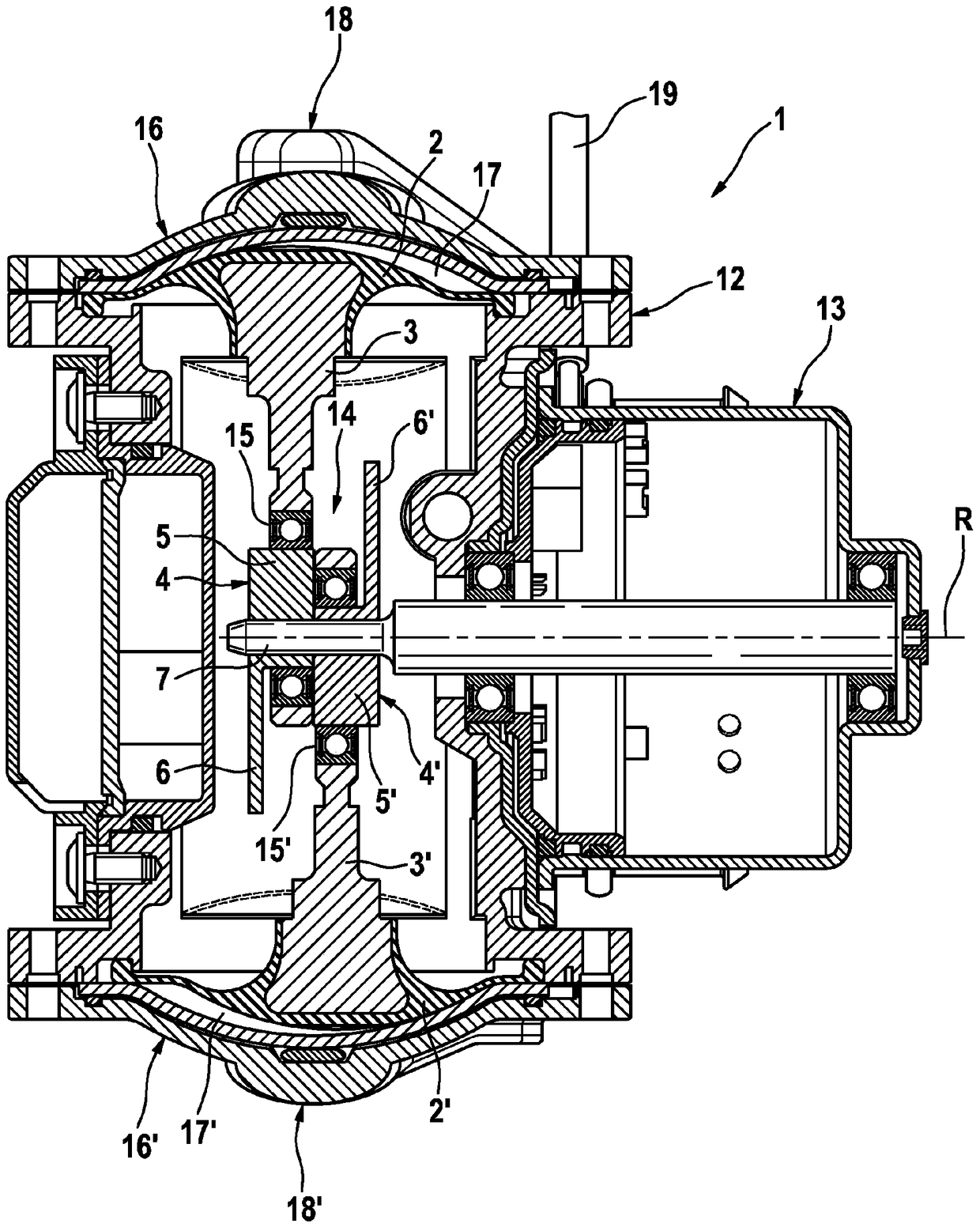
[0029] figure 1

[0030] The known pump device 1 has a pump housing 12 and an electric drive 13 which moves a crankshaft linkage 14 via a drive shaft 7 . The two eccentric elements 4 , 4 ′ are arranged adjacent to one another on the drive shaft 7 and essentially each have an approximately cylindrical bearing element 4 and a counterbalance connected to the bearing element 4 or 4 ′ on one side. Element 5 or 5'. The center points of the two support elements 4, 4' are arranged offset relative to each other at a rotation angle of 180° around the axis of rotation R. In order to keep these prescribed rotational angular positions of the two eccentric elements constant relative to each other, the eccentric elements have as in figure 2 The anti-torsion structure described in. The crankshaft linkage 14 has two connecting rods 3, 3', which are rotatably fixed on bearing elements 5, 5' via ball bearings 15, 15', respectively. The connecting rods 3, 3' end in elastic pressing elements...


PUM


Abstract

A pump assembly for supplying negative pressure to a pneumatic brake booster, wherein the pump assembly has at least two elastic displacement elements which are moved by connecting rods, the connecting rods each being rotatably mounted on an eccentric element. The eccentric element has a bearing seat element and a force element. At least two eccentric elements are secured next to each other on a drive shaft that rotates about an axis of rotation and an interlocking anti-rotation device is provided that determines a defined angular position of the eccentric elements relative to each other about the axis of rotation. In order to improve the ease of assembly and simplify the manufacturability, the anti-rotation device is designed as shaped elements of the bearing seat element in such a way that they engage in each other in an interlocking manner when the eccentric elements are in a defined angular position relative to each other.

Description

technical field [0001] The invention relates to a pump device with a pump housing, in particular for supplying a vacuum for a pneumatic brake booster, wherein the pump device has at least two elastic, connecting rod-driven squeezes elements, wherein the connecting rods are respectively rotatably supported on eccentric elements, wherein the eccentric elements each have a bearing element and a balancing element, wherein at least two eccentric elements are fixed adjacent to each other on On the drive shaft, which rotates about the axis of rotation, there is provided a form-locking, anti-rotational structure which determines a defined rotational angular position of the eccentric elements relative to one another about the axis of rotation. Background technique [0002] Pump devices which are used in motor vehicles for supplementary or sole vacuum supply to pneumatic brake boosters are basically known. [0003] For example, double-membrane pump arrangements are known which have a...

Claims


Application Information

Patent Timeline
Patent Type & Authority Patents(China)
IPC IPC(8): F04B9/04F04B45/04F04B45/047
CPCF04B9/045F04B45/043F04B45/047F16C3/18F16C3/20B60T13/52F04B53/006F04B53/16
Inventor S·克雷布斯J·巴彻尔H·克雷L·米利希奇M·于尔根宁M·尼埃彭伯格J·冈萨雷斯K·塞茨H-M·科佩尔F·佩佐尔德R·菲灵格尔T·欧芬内尔P·维贝尔S·伊姆霍夫M·吕费尔
Owner CONTINENTAL AUTOMOTIVE TECH GMBH
Why Eureka
Try Eureka