Microwave coaxial resonant cavity

A technology of coaxial resonant cavity and resonant cavity, which is applied in the direction of resonators, waveguide devices, electrical components, etc., can solve the problems of inconvenient welding and replacement of probes, and achieve the effect of convenient and quick installation and replacement

Active Publication Date: 2015-12-09
UNIV OF ELECTRONICS SCI & TECH OF CHINA
View PDF3 Cites 3 Cited by
  • Summary
  • Abstract
  • Description
  • Claims
  • Application Information

AI Technical Summary

Problems solved by technology

[0003] Aiming at the defects in the background technology, the present invention proposes a microwave coaxial resonant cavity, which can solve the problem of inconvenient welding and replacement of probes in the background technology

Method used


Image

  • Microwave coaxial resonant cavity
  • Microwave coaxial resonant cavity

Examples


Embodiment Construction

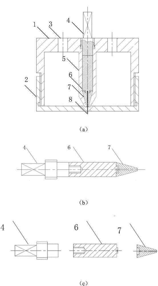
[0012] The present invention will be further introduced below in conjunction with the accompanying drawings.

[0013] like figure 2 As shown in (a), a microwave coaxial resonant cavity provided by the present invention includes a cavity upper cover 1, a cavity 2, a through hole 3 located on the cavity upper cover 1, and a hollow metal column 5, and is characterized in that , also includes a clamping device located in the hollow metal column 5 and fitted with the hollow metal column, the clamping device includes an upper bolt 4, a middle solid metal column 6 and a lower metal cone 7, the bolt 4 Fitted with the solid metal post 6, the solid metal post 6 has a protrusion for positioning, and the metal cone 7 has a groove for positioning that matches the protrusion on the solid metal post. 4. It is connected to the upper cover of the cavity through threads. The metal cone 7 is composed of two identical parts. There is a through hole in the center of the metal cone 7 for position...


PUM


Abstract

The invention relates to a microwave coaxial resonant cavity and belongs to the technical field of measurement of microwave band electromagnetic parameters of materials. The microwave coaxial resonant cavity includes a cavity upper cover, a cavity body, through holes, a hollow metal column and a clamping device which is located in the hollow metal column and is attached to the hollow metal column; the clamping device includes a bolt, a solid metal column and a metal cone; the bolt is attached to the solid metal column; the solid metal column is provided with a protrusion used for positioning; a groove which is matched with the protrusion of the solid metal column is formed in the metal cone; the bolt is connected with the cavity upper cover through a screw thread; the metal cone is composed of two completely-identical parts; a through hole used for positioning a metal probe is formed at the center of the metal cone; the through hole at the center of the metal cone, a through hole at the bottom of the hollow metal column and a through hole at the bottom of the cavity body of the resonant cavity are located at the same axis; and the hollow metal column electrically contacts with the metal probe. With the microwave coaxial resonant cavity of the invention adopted, the installation and replacement of the metal probe can be facilitated, and the metal probe can be located at the center of the resonant cavity assuredly.

Description

technical field [0001] The invention belongs to the technical field of measuring electromagnetic parameters of materials in the microwave band, and in particular relates to a microwave coaxial resonant cavity. Background technique [0002] In the existing 1 / 4λ coaxial resonant cavity with bottom opening, the tip of the scanning probe is located at the center conductor of the resonant cavity and slightly beyond the small hole of the metal shielding layer at the bottom of the cavity, so that the cavity can shield the divergent wave and the tip can form a withered field, which confines the microwave on the needle tip to an extremely small micro-region, and its resonant cavity with a specific size makes the measured electromagnetic material respond to electromagnetic waves of a specific frequency band. The structure of the existing microwave coaxial resonator is as follows: figure 1 As shown, among them, in order to make the measurement results more accurate, the needle tip nee...

Claims


Application Information

Patent Timeline
Patent Type & Authority Applications(China)
IPC IPC(8): H01P7/04H01P7/06
Inventor 向勇蒋常龙王聪
Owner UNIV OF ELECTRONICS SCI & TECH OF CHINA
Why Eureka
Try Eureka