
Host machine of novel oil injection sliding vane air compressor

A technology of air compressors and sliding vanes, which is applied in the direction of machines/engines, mechanical equipment, liquid fuel engines, etc., can solve the problems of low volumetric efficiency, long suction path, and large suction resistance, and achieve high volumetric efficiency and suction Short air path and low inhalation resistance

Active Publication Date: 2015-12-09
NANJING SHANGAIR MACHINERY MFG
View PDF7 Cites 9 Cited by
  • Summary
  • Abstract
  • Description
  • Claims
  • Application Information

AI Technical Summary

Problems solved by technology

[0004] The technical problem to be solved by the present invention is that, aiming at the above-mentioned defects of the main engine of the sliding vane air compressor in the prior art, such as long suction path, large suction resistance, low volumetric efficiency, and serious leakage when the rotor rotates axially, it provides a A new oil-injected sliding vane air compressor main unit with short suction path, small suction resistance, high volumetric efficiency and no leakage when the rotor rotates axially

Method used


Image

  • Host machine of novel oil injection sliding vane air compressor
  • Host machine of novel oil injection sliding vane air compressor
  • Host machine of novel oil injection sliding vane air compressor

Examples


Embodiment Construction

[0030] In order to make the object, technical solution and advantages of the present invention clearer, the present invention will be further described in detail below in conjunction with the accompanying drawings and embodiments. It should be understood that the specific embodiments described here are only used to explain the present invention, not to limit the present invention.

[0031] In the preferred embodiment provided by the present invention, a new oil-injected sliding vane air compressor main body includes a cylinder 1, a rotor 2 and a sliding vane 3;

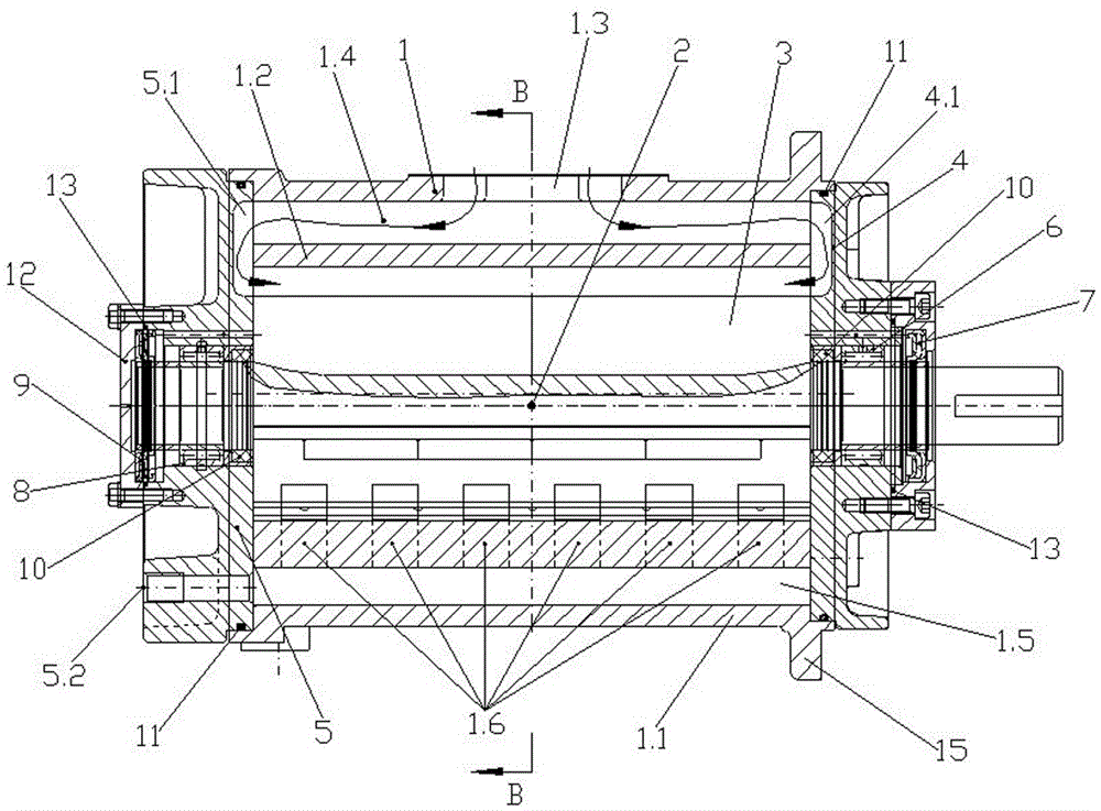
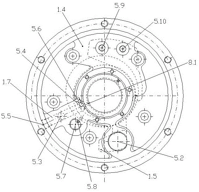
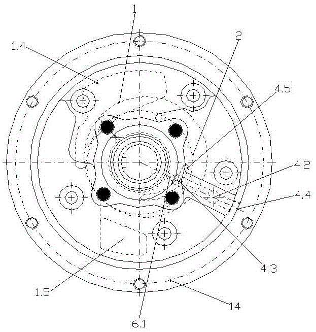
[0032] Such as figure 1 As shown, the above-mentioned cylinder 1 includes a casing 1.1 and an interlayer 1.2 arranged inside the casing 1.1. The bottom end of the casing 1.1 is provided with a mounting foot 15, and the casing 1.1 is also provided with a radial air inlet 1.3, and the interlayer 1.2 The top and bottom ends of the top and bottom of the casing are respectively provided with an axially penetrating air int...


PUM


Abstract

The invention discloses a host machine of a novel oil injection sliding vane air compressor. An air cylinder comprises a shell and an interlayer. The shell is provided with a radial air inlet, and an air inlet cavity is arranged between the top of the interlayer and the shell; an air exhaust cavity is arranged between the bottom of the interlayer and the shell. The bottom of the interlayer is provided with inner air exhaust openings. The front end face and the rear end face of the shell are provided with a front end cover and a rear end cover respectively. The front end cover and the rear end cover are provided with a front end cover air suction cavity and a rear end cover air suction cavity respectively. A rotor is eccentrically arranged in the interlayer. The front shaft neck of the rotor is sleeved with a front bearing and a front shaft seal from front to back sequentially. The rear shaft neck of the rotor is sleeved with a rear bearing and a rear shaft seal from front to back sequentially. The host machine of the novel oil injection sliding vane air compressor is short in air suction path and high in volume efficiency, and is capable of ensuring that no leakage occurs when the rotor rotates axially and effectively avoiding the trouble of shaft sticking when a sliding vane air compressor is started at low temperature. The host machine of the novel oil injection sliding vane air compressor further has the advantages of being low in manufacture cost, small in manufacture difficulty and convenient to maintain.

Description

technical field [0001] The invention relates to the field of vane air compressors, in particular to a novel oil-injected vane air compressor host. Background technique [0002] The oil-injected vane air compressor (hereinafter referred to as the vane machine) and the oil-injected screw air compressor (hereinafter referred to as the screw air compressor) are both rotary compressors. Compared with the two, the former has a simpler structure and a better stress condition , for example, the rotor of the vane machine has no axial load, and due to the balance of multiple internal compression units, its radial force is also much smaller than that of the twin-screw compressor; the internal leakage of the vane machine is also smaller than that of the screw machine, so there is no need to use High speed to reduce the relative leakage loss coefficient, so the energy efficiency is better than screw machine. The service life of the sliding vane machine is longer, more than 2.5 times t...

Claims


Application Information

Patent Timeline
IPC IPC(8): F04C18/344F04C29/02
Inventor 顾余舜顾晓宁
Owner NANJING SHANGAIR MACHINERY MFG
Learn More