Positioning and clamping device for inner hole grinding

A positioning clamping and grinding technology, which is applied in the direction of grinding the workpiece support, etc., can solve the problems of complex structure of the positioning clamping device, affecting inner hole grinding, etc., and achieves the effects of convenient loading and unloading, simplified structure, and convenient adjustment

Inactive Publication Date: 2015-12-09
LUOYANG BEARING SCI & TECH CO LTD
View PDF6 Cites 2 Cited by
  • Summary
  • Abstract
  • Description
  • Claims
  • Application Information

AI Technical Summary

Problems solved by technology

[0004] The object of the present invention is to provide an inner hole grinding positioning clamping device that directly provides a pressing force for the workpiece to be pressed on the tip through a spring, so as to solve the complex structure of the positioning clamping device in the prior art, which affects the inner hole. grinding problem

Method used


Image

  • Positioning and clamping device for inner hole grinding

Examples


Embodiment Construction

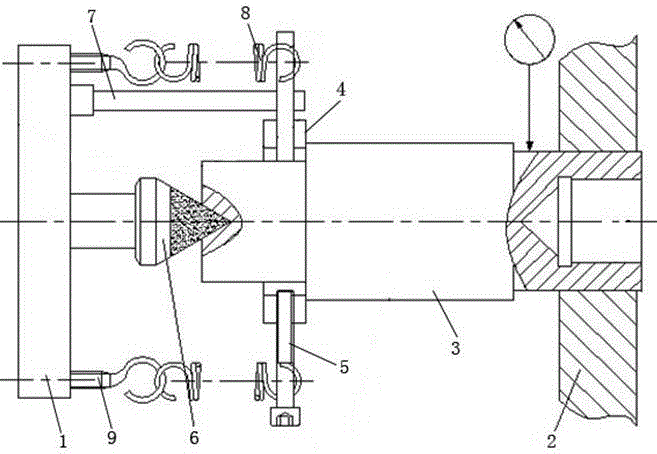
[0011] Embodiment 1 of the inner hole grinding positioning and clamping device of the present invention: as figure 1 As shown, it includes the fixed seat 1. The fixed seat 1 rotates synchronously with the spindle of the grinding machine. The spindle tip 6 extends to the right perpendicular to the fixed seat 1 and passes through the center of the fixed seat 1 to rotate and assemble with the fixed seat 1. The spindle tip 6 is fixed. And as a positioning reference, the fixed seat 1 is provided with two or more hooks 9 around the spindle top 6. The hooks 9 are screwed on the fixed seat by threads and can be adjusted in the left and right directions. The internal hole grinding positioning clamping device It also includes a clamping structure for clamping the workpiece 3. The clamping structure includes two push rods 5 that radially press against the outer peripheral surface of the workpiece 3 to clamp the workpiece. In this embodiment, the clamping structure includes a snap ring 4, ...


PUM


Abstract

The invention provides a positioning and clamping device for inner hole grinding. The device comprises a fixing base fixedly connected with a main shaft and a clamping structure for clamping a workpiece. The clamping structure comprises two or more ejector rods which jack the peripheral face of the workpiece in the radial direction so as to clamp the workpiece. The positioning and clamping device for inner hole grinding further comprises tension springs used for providing tension for the workpiece so as to tightly press the workpiece to the centre of the main shaft, wherein one end of each tension spring is connected with the fixing base, the other end of each tension spring is hooked to the corresponding ejector rod, and the tension springs are perpendicular to the ejector rods. According to the positioning and clamping device for inner hole grinding, the tension springs directly pull the fixing base and the ejector rods used for clamping the workpiece, the springs are perpendicular to the ejector rods so that the elastic acting force of the springs can keep parallel with the axis of the workpiece all the time, in this way, the structure of the whole device is greatly simplified, and the manufacturing and assembly difficulty is lowered. Because the elastic force of the springs keeps parallel with the axis of the workpiece, an accurate stress direction of the workpiece is ensured, deflection torque is avoided, and workpiece grinding precision is high.

Description

technical field [0001] The invention relates to a positioning and clamping device for inner hole grinding. Background technique [0002] When grinding the inner hole of rigid shaft parts, the chuck is generally used to clamp one end of the shaft, and the other end of the center frame supports the shaft to align and then grinds the inner hole, or two center frames are used to support the two ends of the shaft respectively, and the center frame is used to align the other end of the shaft. Grinding the inner hole afterward, but both methods have certain problems. The first method is affected by the accuracy of the machine tool chuck itself and the accuracy of the chuck clamping surface, so it is difficult to guarantee the grinding accuracy of the inner hole. When the two methods are used, the shaft parts will move axially, and the center frame close to the head frame is often subjected to torque force, which also has a certain impact on the grinding of the inner hole. [0003]...

Claims


Application Information

Patent Timeline
Patent Type & Authority Applications(China)
IPC IPC(8): B24B41/06
CPCB24B41/062
Inventor 李彦帖江涛
Owner LUOYANG BEARING SCI & TECH CO LTD
Why Eureka
Try Eureka