
Method and system for testing distortion rate of camera

A test method and test system technology, applied in the direction of image communication, television, electrical components, etc., can solve the problems of not being able to realize online continuous multiple tests, difficulty in popularization, and high cost, and achieve shortened correction time, low cost, and saving the effect of time

Inactive Publication Date: 2015-12-02
SHENZHEN HANGSHENG ELECTRONICS
View PDF5 Cites 9 Cited by
  • Summary
  • Abstract
  • Description
  • Claims
  • Application Information

AI Technical Summary

Problems solved by technology

Most of the current methods of testing distortion rate are integrated on bulky equipment, and the investment cost is very high, so it is not easy to popularize
And each clamping can only measure the distortion rate of one point, and it has not been able to realize multiple online continuous tests

Method used


Image

  • Method and system for testing distortion rate of camera
  • Method and system for testing distortion rate of camera
  • Method and system for testing distortion rate of camera

Examples


Embodiment Construction

[0016] The present invention will be described in further detail below in conjunction with the accompanying drawings and embodiments.

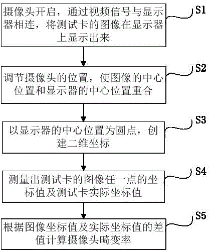
[0017] like figure 1 As shown, the camera distortion rate testing method of the present invention comprises the following steps:

[0018] S1: The camera is turned on, connected to the monitor through the video signal, and the image of the test card is displayed on the monitor;

[0019] S2: adjust the position of the camera so that the center position of the image coincides with the center position of the display;

[0020] S3: Create two-dimensional coordinates with the center of the display as the dot;

[0021] S4: Measure the coordinate value of any point on the image of the test card and the actual coordinate value of the test card;

[0022] S5: Calculate the camera distortion rate according to the difference between the image coordinate value and the actual coordinate value.

[0023] In the present embodiment, in step S1, the test card ...


PUM


Abstract

The invention provides a method and a system for testing the distortion rate of a camera, and belongs to the field of camera correction. The method for testing the distortion rate of the camera comprises the steps of turning on the camera, connecting the camera to a display through video signals, and displaying an image of a test card on the display; adjusting the position of the camera, and enabling the central position of the image to be overlapped with the central position of the display; establishing a two-dimensional coordinate system by taking the central position of the display as a dot; measuring coordinate values of any point of the image of the test card and actual coordinate values of the test card; and calculating the distortion rate of the camera according to the difference between the image coordinate values and the actual coordinate values. The method provided by the invention is simple, efficient, effective and low in cost. In addition, multiple times of continuous measurement online can be realized, the work efficiency is improved, and the time is saved, thereby greatly shortening the correction time in a research and development period of the camera.

Description

technical field [0001] The invention relates to the field of camera correction, in particular to a method and system for testing the distortion rate of a camera. Background technique [0002] Nowadays, due to the wide application of cameras in the automotive field, great convenience is provided for drivers. However, due to the increasing angle of the camera, especially the application of a 180-degree wide-angle camera, its distortion rate is also increasing, resulting in a large visual difference between the displayed image and the real scene, which is not conducive to the driver's intuition Therefore, it is often necessary to correct the image. However, the correction will affect the angle of view, resulting in the loss of part of the field of view, especially the excessive correction, which may even cause the angle of view not to meet the requirements. What is the distortion rate after correction, and whether it can meet the field of view requirements and facilitate visu...

Claims


Application Information

Patent Timeline
Patent Type & Authority Applications(China)
IPC IPC(8): H04N17/00
Inventor 覃开宇
Owner SHENZHEN HANGSHENG ELECTRONICS
Learn More