
Photoetching plate and mask correction method

A photolithographic plate and mask technology, applied in optics, originals for photomechanical processing, instruments, etc., can solve the problems of mask pattern processing interference, extended correction time, mask scrapping, etc.

Active Publication Date: 2019-06-18
SEMICON MFG INT (SHANGHAI) CORP +1
View PDF5 Cites 1 Cited by
  • Summary
  • Abstract
  • Description
  • Claims
  • Application Information

AI Technical Summary

Problems solved by technology

However, this approach places the scattering strips on the substrate, which interferes with the processing of the mask pattern, thus risking deposition loss, resulting in mask scrapping and prolonged revision times

Method used


Image

  • Photoetching plate and mask correction method
  • Photoetching plate and mask correction method
  • Photoetching plate and mask correction method

Examples


Embodiment Construction

[0046] Various exemplary embodiments of the present invention will now be described in detail with reference to the accompanying drawings. It should be noted that the relative arrangement of components and steps, the numerical expressions and numerical values ​​set forth in these embodiments do not limit the scope of the invention unless specifically stated otherwise.

[0047] Meanwhile, it should be understood that, for the convenience of description, the dimensions of various parts shown in the accompanying drawings are not drawn in an actual proportional relationship.

[0048] The following description of at least one exemplary embodiment is merely illustrative in nature and is in no way intended to limit the invention, its application, or uses.

[0049] Techniques, methods, and devices known to those of ordinary skill in the relevant art may not be discussed in detail, but where appropriate, such techniques, methods, and devices should be considered part of the authorized ...


PUM


Abstract

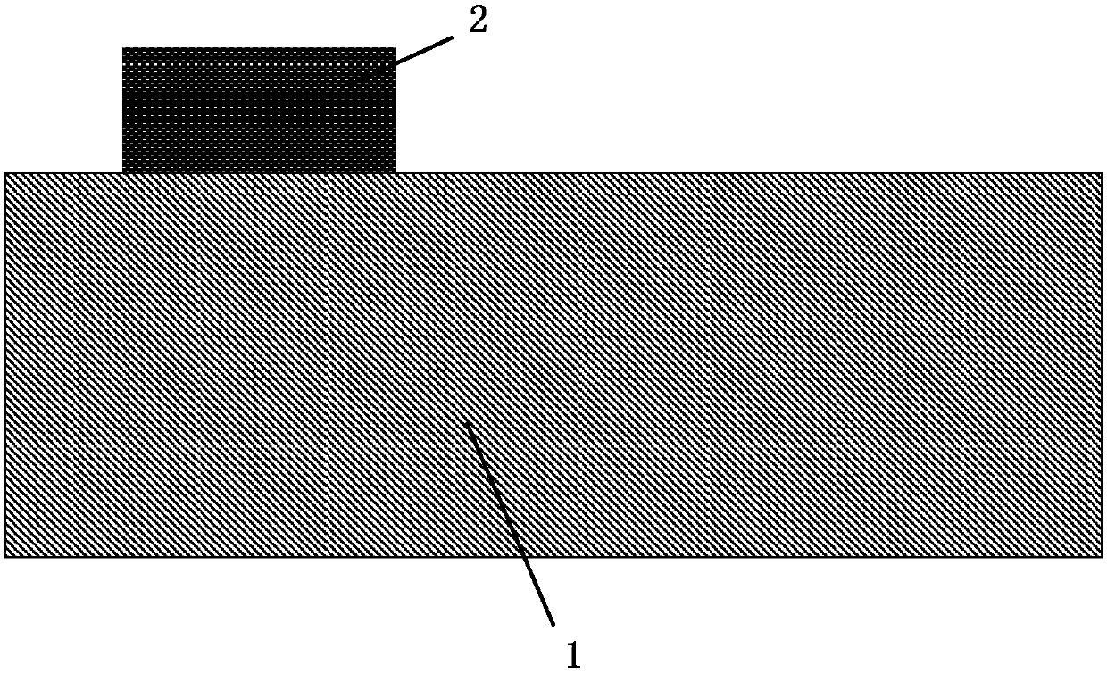
The invention discloses a photoetching plate and a mask correction method, and relates to the technical field of semiconductors. In the mask correction method, a patterned mask is formed on a substrate; the position, embedded in the substrate, of a scattering strip is determined according to the mask; and an opening is formed in the determined position so as to embed the scattering strip into theopening. The scattering strip is embedded into the substrate of the photoetching plate, so that the influence of the scattering strip on the mask pattern can be effectively avoided, the deposition loss is reduced, the correcting effect is improved, and the correcting time is shortened.

Description

technical field [0001] The present invention relates to the technical field of semiconductors, and in particular, to a photoresist and a mask correction method. Background technique [0002] Integrated circuit manufacturing technology is a complex process, and the technology is updated rapidly. A key parameter that characterizes integrated circuit manufacturing technology is the minimum feature size, that is, the critical dimension (CD). It is precisely because of the reduction of the critical dimension that it is possible to set millions of devices on each chip. [0003] Lithography is the driving force behind the development of integrated circuit manufacturing processes and one of the most complex technologies. Compared with other single manufacturing technologies, the improvement of lithography technology is of great significance to the development of integrated circuits. Before the photolithography process starts, the pattern needs to be copied to the mask by a specifi...

Claims


Application Information

Patent Timeline
Patent Type & Authority Applications(China)
IPC IPC(8): G03F1/36
CPCG03F1/36G03F1/80G03F1/84G03F1/72
Inventor 张健澄吴苇张晨波
Owner SEMICON MFG INT (SHANGHAI) CORP
Learn More