


Quick Research
Generate reliable direction feasibility study reports for your R&D in just a few steps.

Technical Q&A
Discover and master advanced knowledge NOW. Basics, ideas, possibilities, all at once.

Find Solutions
As an expert in R&D theories, this can generate solutions to your technical problems instantly.

Evaluate Feasibility
Analyze your overall solution with one click, know your potential R&D risks in advance.

Monitor Landscape
Get weekly tech updates, stay abreast of the latest tech innovations and key insights.
Converter rectifier
A rectifier and converter technology, applied in the field of electric power, can solve the problem of high cost of rectifier devices and achieve the effect of reducing the cost of devices
- Summary
- Abstract
- Description
- Claims
- Application Information
AI Technical Summary
Problems solved by technology
Method used
Image

Examples
Embodiment 1
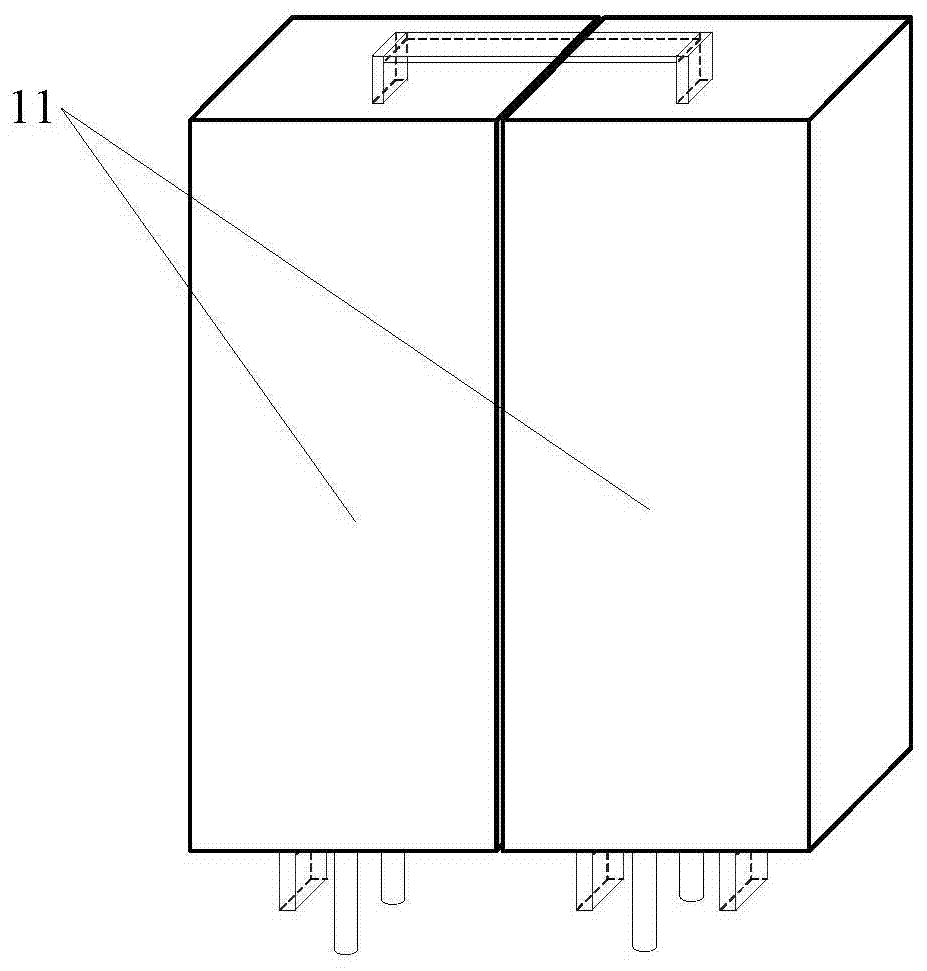
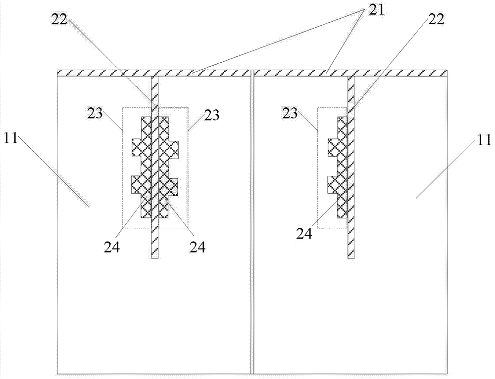
[0018] figure 1 It is a schematic diagram of the external structure of an embodiment of the converter rectifying device provided by the present invention. figure 2 for figure 1 A schematic cross-sectional view of the converter rectifier shown. like figure 1 and figure 2 As shown, the converter rectifying device of this embodiment may include: two rectifying modules 11 .
[0019] Please refer to Figure 1-Figure 2 , the two rectifier modules 11 both include a module backplane 21 and a water-cooled substrate 22 fixedly installed on the module backplane 21, the difference is that the two sides of the water-cooled substrate 22 in one rectifier module 11 are each pasted with a single-phase structure. At least one insulated gate bipolar transistor (IGBT for short) 24 of the rectifier bridge 23, while the water-cooled substrate 22 in the other rectifier module 11 has only one side surface pasted with a group of at least one single-phase rectifier bridge 23. IGBT24.
[0020] ...
Embodiment 2
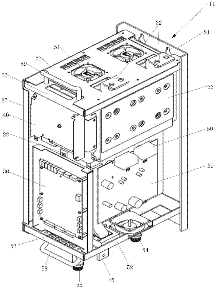
[0023] image 3 It is a perspective view of a rectifier module in another embodiment of the converter rectifier device provided by the present invention. Figure 4 for image 3 An exploded view of the perspective view of the rectifier module shown. Figure 5 for image 3 Electrical schematic diagram of the converter rectifier shown.
[0024] like image 3 , Figure 4 and Figure 5 As shown, the rectifier module 11 in the converter rectifier device of this embodiment is figure 1 can also include: fixedly installed on the module backplane 21 (such as image 3 , Figure 4 shown) on the first fixing plate 31 (such as Figure 4 shown) and the DC busbar 32 and the laminated busbar 33 fixedly mounted on the first fixing plate 31 . The positive pole of the laminated busbar 33 is respectively connected to the positive pole of the DC busbar 32 and the single-phase rectifier bridge 23 (eg Figure 5 The positive terminal of the DC output shown in the figure) is electrically con...
PUM
 Abstract
Description
Claims
Application Information
 - R&D Engineer
- R&D Manager
- IP Professional
- Industry Leading Data Capabilities
- Powerful AI technology
- Patent DNA Extraction
Browse by: Latest US Patents, China's latest patents, Technical Efficacy Thesaurus, Application Domain, Technology Topic, Popular Technical Reports.
© 2024 PatSnap. All rights reserved.Legal|Privacy policy|Modern Slavery Act Transparency Statement|Sitemap|About US| Contact US: help@patsnap.com