


Quick Research
Generate reliable direction feasibility study reports for your R&D in just a few steps.

Technical Q&A
Discover and master advanced knowledge NOW. Basics, ideas, possibilities, all at once.

Find Solutions
As an expert in R&D theories, this can generate solutions to your technical problems instantly.

Evaluate Feasibility
Analyze your overall solution with one click, know your potential R&D risks in advance.

Monitor Landscape
Get weekly tech updates, stay abreast of the latest tech innovations and key insights.
Electrical contact quick connector
A technology of electrical contacts and connectors, which is applied in the direction of conductive connection, electrical component connection, connection, etc., to achieve the effects of fast positioning, increased anti-pull-off ability, and increased friction
- Summary
- Abstract
- Description
- Claims
- Application Information
AI Technical Summary
Problems solved by technology
Method used
Image

Examples
Embodiment 1
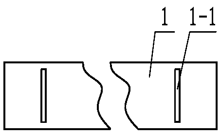
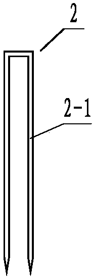
[0044] Figure 1 to Figure 4 The shown electrical contact quick connector is composed of a strip body 1 and a conductive plug-in piece 2, wherein the strip body 1 is used to enclose the cable 3, and the conductive plug-in piece 2 is inserted into the strip body 1 and the cable 3 to fasten The belt body 1 is connected to the cable 3; the parts near the two ends of the belt body 1 are respectively provided with jacks 1-1 for inserting the conductive connectors 2, see figure 1 ;Such as figure 2 and image 3 As shown, the conductive connector 2 of this embodiment is a rigid conductive connector, the conductive connector 2 is flat, and the conductive connector 2 is bent symmetrically in the middle according to the position of the jack 1-1 of the belt body 1 Two insertion parts 2-1 are formed, and the end of the insertion part 2-1 is a cone, and its sharpness is limited to be able to pierce the belt around the cable and go deep into the inside of the cable to directly contact the...
Embodiment 2
[0047] In order to increase the current passing capacity of electrical contacts or reduce the surface contact resistance, when the pressure on the surface of the connector is constant, increase the number of connectors or directly increase the contact area between the surface of the connector and the surface of the cable. Therefore, the contact resistance is smaller and the electrical contact performance of the electrical contacts is better; when the number of connectors is increased, the number or width of the strip body 4 can be increased correspondingly, and multiple sets of jacks 4 can be opened on the wider strip body 4 -1, see Figure 5 . Other features are the same as in Embodiment 1.
Embodiment 3
[0049] Such as Figure 6 As shown, the conductive connector 6 of this embodiment is an elastic connector. It is worth mentioning that, in this embodiment, a plurality of jacks are correspondingly opened on the overlapped portion of the belt body 5 . Figure 6 The cable 7 in the cable is a non-insulated single-strand wire core wire. When making an electrical contact, two bare wires are bound together with a belt body 5, and then the connector 6 is embedded between the two wires. Make them have good electrical connection characteristics. At this time, the material of the strip body 5 is a good conductor material. In order to better maintain a good electrical connection state, the contact area between the strip body 5 and the conductor and the conductive connector 6 can be increased. number, and after the conductive plug 6 is driven into the space between the two conductors using an auxiliary tool, the ends are also bent towards each other so that they are tightly pressed against...
PUM
 Abstract
Description
Claims
Application Information
 - R&D Engineer
- R&D Manager
- IP Professional
- Industry Leading Data Capabilities
- Powerful AI technology
- Patent DNA Extraction
Browse by: Latest US Patents, China's latest patents, Technical Efficacy Thesaurus, Application Domain, Technology Topic, Popular Technical Reports.
© 2024 PatSnap. All rights reserved.Legal|Privacy policy|Modern Slavery Act Transparency Statement|Sitemap|About US| Contact US: help@patsnap.com