
Four-redundancy signal monitoring method and device

A signal monitoring, four-redundancy technology, applied in general control systems, control/regulation systems, instruments, etc., can solve the problem of selecting large and small monitoring thresholds, reducing the impact and solving the error of the redundant signal. Use and solve the effect of wrong judgment

Active Publication Date: 2018-06-29
XIAN AIRCRAFT DESIGN INST OF AVIATION IND OF CHINA
View PDF6 Cites 0 Cited by
  • Summary
  • Abstract
  • Description
  • Claims
  • Application Information

AI Technical Summary

Problems solved by technology

Therefore, the strategy of changing the threshold cannot solve the contradiction between choosing a large and small monitoring threshold, and because the variable threshold makes the monitoring threshold wider, it also introduces the problem of common thresholds.

Method used


Image

  • Four-redundancy signal monitoring method and device
  • Four-redundancy signal monitoring method and device

Examples


Embodiment Construction

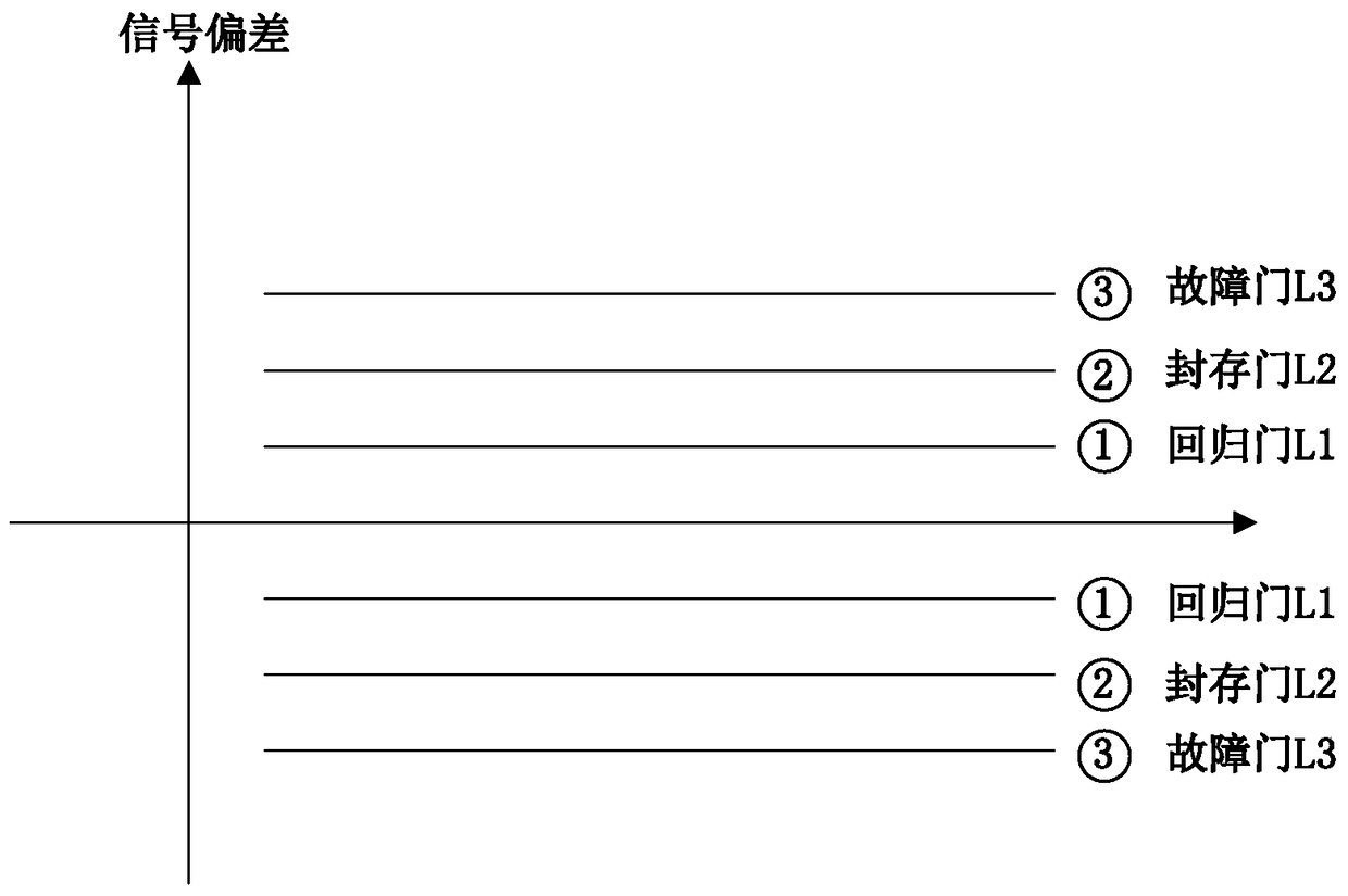
[0015] Combine below figure 2 The present disclosure is described in detail. figure 2 is a schematic diagram illustrating a three-door approach to redundancy signal monitoring according to an embodiment of the present disclosure.

[0016] like figure 2 As shown, three monitoring thresholds are set for four-redundancy signal monitoring. That is, the regression gate L1 with the minimum threshold value, the storage gate L2 with the intermediate threshold value, and the failure gate L3 with the maximum threshold value.

[0017] In the monitoring of the four-redundancy signal using these three gates, the following monitoring method is used.

[0018] When the absolute value of the difference between one of the four redundancy signals and the voting value is greater than the fault gate L3 for more than the first predetermined time, it is determined that the signal is permanently faulty, and the use of the signal is discarded. The first predetermined time is for example but not...


PUM


Abstract

Provided are a four-redundancy signal monitoring method and device. The method includes: setting three monitoring thresholds for four-redundancy signal monitoring, namely, a return gate L1 with a minimum threshold value, a storage gate L2 with an intermediate threshold value, and a fault gate L3 with a maximum threshold value; When the absolute value of the difference between one of the signals and the voting value of the redundancy signal is greater than the fault gate L3 and continuously exceeds the first predetermined time, it is determined that the signal is permanently faulty and the use is abandoned; when the absolute value of the difference between one of the signals and the voting value of the four redundancy signals When the absolute value of the difference between the determined abnormal signal and the voting value returns to the return gate L1 and continues for more than the third predetermined time, it is determined again Signal is normal. The monitoring method realizes the initial diagnosis and confirmation process of redundant signal faults, reduces false alarms and false alarms in fault diagnosis, ensures the accuracy of high-redundant signal acquisition, and slows down the speed of fault degradation of redundant signals.

Description

technical field [0001] The present disclosure relates to fault monitoring of a fly-by-wire flight control system, in particular to a three-door method and device for four-redundancy signal fault monitoring. Background technique [0002] The application of fly-by-wire flight control system provides an opportunity to optimize aircraft performance and reduce the burden on pilots, but it also brings certain risks. For example, a failure of the flight control computer or sensors in the fly-by-wire flight control system would immediately render the aircraft uncontrollable. In order to solve this problem, redundant fault-tolerant architecture is generally adopted in the design of fly-by-wire flight control system. That is, there is a margin in the configuration from the flight control computer, sensors to actuators. [0003] Redundancy management technology is the key to fly-by-wire flight control system design. Its purpose is to improve the safety and reliability of the fly-by-...

Claims


Application Information

Patent Timeline
Patent Type & Authority Patents(China)
IPC IPC(8): G05B9/03
Inventor 杜永良
Owner XIAN AIRCRAFT DESIGN INST OF AVIATION IND OF CHINA
Learn More