
A voltage drop detection method suitable for grid voltage with large harmonic content

A technology of grid voltage and voltage sag, applied in the direction of measuring current/voltage, measuring electrical variables, measuring devices, etc., can solve the problems of long delay time, no harmonic suppression ability, and great harmonic influence, and achieve anti-harmonic Strong interference ability, the effect of ensuring accuracy and stability

Active Publication Date: 2018-07-06
NAVAL UNIV OF ENG PLA +1
View PDF13 Cites 0 Cited by
  • Summary
  • Abstract
  • Description
  • Claims
  • Application Information

AI Technical Summary

Problems solved by technology

[0031] Its detection structure diagram is as follows figure 2 , this method can achieve no difference between positive and negative sequences, but the calculated positive sequence amplitude is delayed by T / 4 power frequency period, the response is slow, the judgment process is long, and it is easy to cause instantaneous overcurrent, and the harmonics have a great impact on it , the longer delay time and no harmonic suppression ability is a major criticism of this type of method, the dynamic performance and stability when used alone are difficult to meet the actual needs
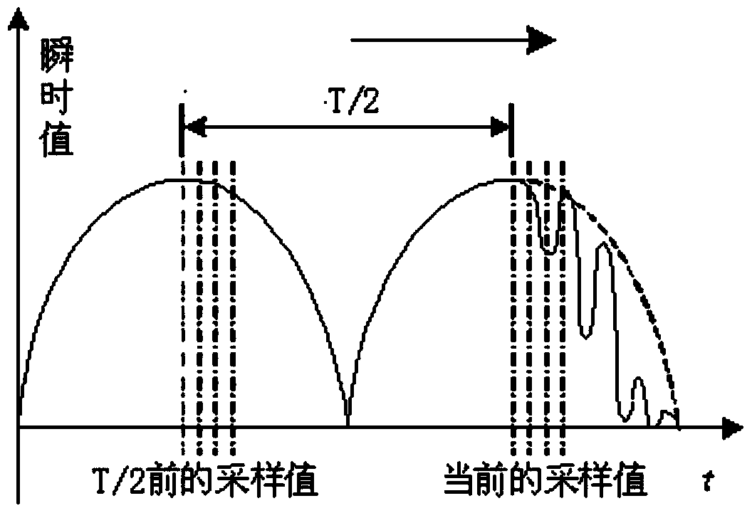
[0032] To sum up, it can be seen that the traditional steady-state judgment cannot avoid the instantaneous overcurrent phenomenon caused by the positive sequence amplitude delay and slow response, and has no harmonic suppression ability, and the harmonic has a great influence on the judgment result
[0033] Although the traditional instantaneous judgment can solve the instantaneous overcurrent phenomenon, it is not ideal for judging the situation where the voltage drops slowly for many times.

Method used


Image

  • A voltage drop detection method suitable for grid voltage with large harmonic content
  • A voltage drop detection method suitable for grid voltage with large harmonic content
  • A voltage drop detection method suitable for grid voltage with large harmonic content

Examples


Embodiment Construction

[0061] Below in conjunction with accompanying drawing and specific embodiment the present invention is described in further detail:

[0062] Such as Figure 4 As shown, the present invention uses a combination of steady-state judgment and instantaneous judgment for detection.

[0063] The positive and negative sequence voltage modulus in the steady state judgment method of the present invention is obtained by improving the traditional T / 4 delay method, and its calculation process is:

[0064] The grid voltage is transformed by equal-amplitude Clarke to obtain the signal

[0065]

[0066] The signal e α(t) 、e β(t) The signal before 1 / 4 period is expressed as

[0067]

[0068] signal e α(t) 、e β(t) by formula

[0069]

[0070] After filtering, differential for delay compensation, and then with the signal e before 1 / 4 cycle α(t-T / 4) 、e β(t-T / 4) The sum and difference operation is carried out, so that the positive and negative sequence components of the voltage a...


PUM


Abstract

The present invention relates to the electric energy transformation technology field, in particular to a voltage drop detection method suitable for a power grid voltage large harmonic content. The method comprises the steps of real-timely detecting a power grid voltage, calculating a positive sequence module value eP and a negative sequence module value eN of the power grid voltage, and carrying out the steady state judgment according to a calculation result; real-timely detecting the power grid voltage, calculating the voltage components e alpha and e beta of the power grid voltage in an alpha-beta stationary reference frame, carrying out the instant judgment according to the calculation result. When the instant judgment is used to limit an instant overcurrent, and the steady state judgment is used to determine a reactive current, the instant judgment pays attention to the rapidity, and the steady state judgment pays attention to the stability and accuracy. The two methods are combined to use, and make up the insufficiency mutually, thereby guaranteeing the accuracy and the stability of a judgment result.

Description

technical field [0001] The invention relates to the technical field of electric energy conversion, in particular to a voltage drop detection method suitable for grid voltage with large harmonic content. Background technique [0002] With the scarcity of resources and environmental pollution, the rapid development of new energy power generation has become an unstoppable trend. However, the increase in installed capacity has increased the proportion of its power generation to the grid power supply, so the impact of new energy grid-connected power generation on grid stability is also As it increases, the impact of grid faults on the operation status of grid-connected inverters and the stability of the grid must be considered. Therefore, the State Grid Corporation of China requires all grid-connected inverters to have a certain low-voltage ride-through capability. Low Voltage Ride-through (LVRT) technology in the grid-connected power generation system means that when the voltage...

Claims


Application Information

Patent Timeline
Patent Type & Authority Patents(China)
IPC IPC(8): G01R19/00
Inventor 鄢盛辉武美娜周亮王兰胡安
Owner NAVAL UNIV OF ENG PLA
Learn More