
Automatic oil filling device of oil rotary vane vacuum pump

A rotary vane vacuum pump, automatic refueling technology, applied to parts of pumping devices for elastic fluids, rotary piston pumps, pumps, etc., can solve problems such as large production impact, lower oil level, vacuum pump damage, etc., to achieve operation Convenience, impact reduction, and productivity-enhancing effects

Inactive Publication Date: 2015-12-02
GUILIN STRONG MICROELECTRONICS
View PDF5 Cites 0 Cited by
  • Summary
  • Abstract
  • Description
  • Claims
  • Application Information

AI Technical Summary

Problems solved by technology

[0002] Oil-type rotary vane vacuum pump automatic refueling device is widely used in metallurgy, machinery, military industry, electronics, chemical industry, light industry, petroleum and pharmaceutical and other production and scientific research departments. The vacuum pump must ensure that the oil level is normal during operation. After a period of operation, the vacuum pump The oil will be lost and the oil level will decrease. If it is not added in time and continues to run, it may cause damage to the vacuum pump
[0003] When adding oil to the vacuum pump in actual production, the vacuum pump must be stopped, unscrew the sealing screw of the filling port, insert the funnel into the filling port, and slowly pour the oil into the pump body with a spoon. If the pump is still running, the positive pressure in the pump will decrease. The vacuum pump oil is sprayed out from the refueling port. The refueling work is troublesome and time-consuming. During the refueling period, the vacuum pump stops and cannot provide vacuum. The equipment that needs vacuum on the production line is forced to stop and wait, which has a great impact on production.

Method used


Image

  • Automatic oil filling device of oil rotary vane vacuum pump

Examples


Embodiment Construction

[0014] Below in conjunction with accompanying drawing, technical scheme of the present invention will be further described:

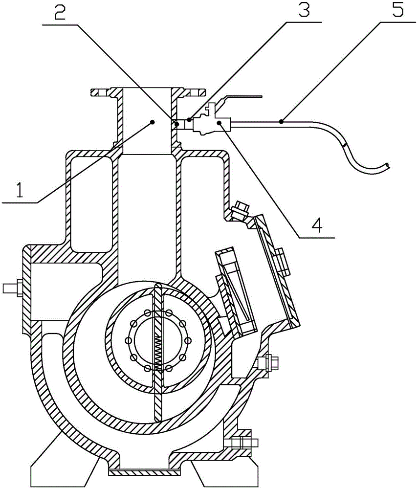
[0015] The automatic refueling device of the oil-type rotary vane vacuum pump of the present invention is mainly composed of an oil inlet 2, a metal pipe 3, a flow control valve 4, and an oil suction pipe 5 arranged on the outer wall below the vacuum suction port 1.

[0016] One end of the metal pipe 3 is connected to the oil inlet 2. Preferably, the connection mode between the oil inlet 2 and the metal pipe 3 is threaded connection, the oil inlet 2 is an internal thread, and the metal pipe 3 is a corresponding Matching external thread; the other end is connected to the flow control valve 4, which is a switch for controlling the flow rate of the vacuum pump oil flowing through; one end of the oil suction pipeline 5 is connected to the flow control valve 4, and the other end is a free The end extends into the vacuum pump oil drum, such as figure 1 shown...


PUM


Abstract

The invention discloses an automatic oil filling device of an oil rotary vane vacuum pump. The device comprises an oil inlet formed in an outer wall below a vacuum air suction port, a metallic pipe, a flow control valve and an oil suction pipe, wherein one end of the metallic pipe is connected with the oil inlet and the other end of the metallic pipe is connected with the flow control valve; one end of the oil suction pipe is connected with the flow control valve and the other end of the oil suction pipe is a free end which stretches into a vacuum pump oil barrel. The automatic oil filling device of the oil rotary vane vacuum pump can automatically fill oil to the vacuum pump under the situation of continuous operation without shutdown, vacuum pump oil is sucked in by using negative pressure produced by the vacuum pump air suction port during operation, the flow is adjusted through the flow control valve, the operation is convenient, simple and quick to perform, the influence on production is further reduced and the production efficiency can be effectively improved to a certain extent.

Description

technical field [0001] The invention relates to an auxiliary facility of a vacuum pump, in particular to an automatic oiling device for an oil-type rotary vane vacuum pump. Background technique [0002] Oil-type rotary vane vacuum pump automatic refueling device is widely used in metallurgy, machinery, military industry, electronics, chemical industry, light industry, petroleum and pharmaceutical and other production and scientific research departments. The vacuum pump must ensure that the oil level is normal during operation. After a period of operation, the vacuum pump The oil will be lost and the oil level will decrease. If it is not added in time and continues to run, it may cause damage to the vacuum pump. [0003] When adding oil to the vacuum pump in actual production, the vacuum pump must be stopped, unscrew the sealing screw of the filling port, insert the funnel into the filling port, and slowly pour the oil into the pump body with a spoon. If the pump is still run...

Claims


Application Information

Patent Timeline
IPC IPC(8): F04C29/00F04C18/344
Inventor 朱金华李勇昌彭顺刚邹锋王常毅
Owner GUILIN STRONG MICROELECTRONICS
Learn More