
Air buoyancy flying equipment

A technology of air buoyancy and equipment, applied in the direction of rigid spacecraft, airbag layout, etc., can solve the problems of resource consumption and land occupation

Pending Publication Date: 2015-12-02
文祥
View PDF7 Cites 0 Cited by
  • Summary
  • Abstract
  • Description
  • Claims
  • Application Information

AI Technical Summary

Problems solved by technology

[0013] The present invention uses air buoyancy as the power to make the equipment fly upwards, and uses gravity as the power to fly downwards, so that the equipment can carry people to the destination and realize zero emissions, which solves several problems existing in the existing similar technologies:
[0015] 2. Solve the problem of small cars vying for roads and expanding roads to consume a lot of resources and occupy a lot of land

Method used


Image

  • Air buoyancy flying equipment
  • Air buoyancy flying equipment
  • Air buoyancy flying equipment

Examples


Embodiment Construction

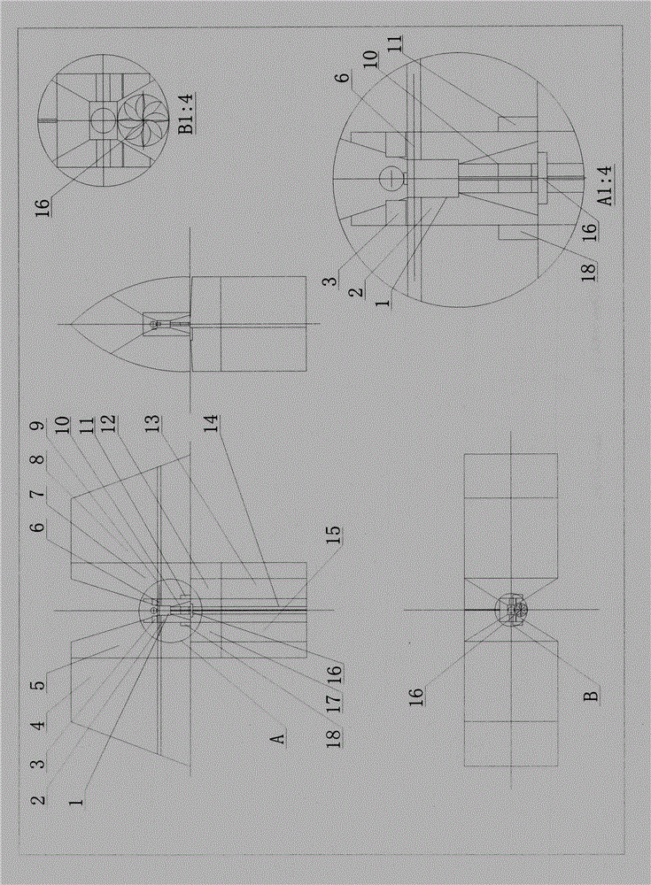
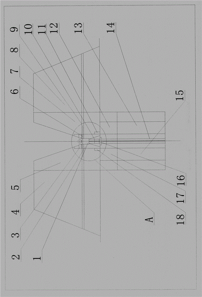
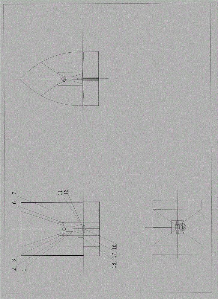
[0040] An air buoyancy flight equipment using air buoyancy as lift-off power, comprising a safety flight chamber 1, a central airbag 2, a control panel 3, a left wing auxiliary airbag 4, a left wing main airbag 5, left and right wing control arms 6, a right wing main airbag 7, Right wing auxiliary airbag 8, left and right wing control levers 9, left and right tail wing control legs 10, charging and storage device 11, right tail main airbag 12, right tail auxiliary airbag 13, left and right tail control levers 14, left tail auxiliary airbag 15, propeller 16. Left tail main airbag 17, light gas compression device 18; it is characterized in that the safety flight compartment 1 is fixed in the central airbag 2, the control panel 3 is installed on the central airbag 2, and the central airbag 2 passes through the left and right wing control arms 6 and the left and right airbags. Wing control rod 9 links to each other with left wing main airbag 5, left wing auxiliary airbag 4 and righ...


PUM


Abstract

The invention belongs to the field of application of the mechanical technology, the weak current control technology and the physical mechanics technology of aircrafts, and relates to air buoyancy flying equipment. The air buoyancy flying equipment solves the technical problems that firstly, a large amount of energy is consumed by small cars, environment is polluted, and the atmosphere is destroyed; secondly, the small cars occupy highways, a large number of resources are consumed by highway extension, and a large amount of land is occupied; and thirdly, cars cannot pass blocked highways. According to the technical scheme for solving the problems and the main application, through manual or automatic control, the buoyancy of a light air bag in air is adopted as power for levitation flying, light air is compressed to decrease the size of the equipment, and gravity is adopted as power for descending flying; and the air buoyancy flying equipment is a substitute for small communication media, clean energy is adopted, and zero-discharge transportation is achieved.

Description

technical field [0001] The invention relates to the field of application of mechanical technology, weak current control and physical mechanics technology of an aircraft. Background technique [0002] One, the present invention is the comprehensive utilization of several existing practical technologies, the following is the main equipment technical description: [0003] 1. Safe flight cabin 1 is the utilization of existing mature safety protection technology. [0004] 2. The control panel 3 is a comprehensive application of the existing weak current control system and electronic technology. [0005] 3, the control principle of the left and right wings and the left and right empennages is the utilization of existing mechanical mechanics technology. [0006] 4. The charging, supplying and storing device 11 is an application of existing charging, supplying and storing technologies. [0007] 5, propeller 16 is the utilization of existing flight technology. [0008] Two, the e...

Claims


Application Information

Patent Timeline
Patent Type & Authority Applications(China)
IPC IPC(8): B64B1/60B64B1/24
Inventor 文祥
Owner 文祥
Learn More