
Oppositely-rotating shaft-less rim-driven propeller

A technology of rim drive and propeller, which is applied in the direction of rotary propeller, ship propulsion, propulsion components, etc. It can solve the problems of difficult manufacturing, high manufacturing and maintenance costs, and motor size limitations, so as to avoid head-on resistance and winding , good lateral stability and high propulsion efficiency

Active Publication Date: 2015-12-02
WUHAN UNIV OF TECH
View PDF8 Cites 41 Cited by
  • Summary
  • Abstract
  • Description
  • Claims
  • Application Information

AI Technical Summary

Problems solved by technology

This hubless structure is beneficial to reduce resistance and solve the problem of debris or cable entanglement, but limited by the size of the motor, the power of the propeller is limited
Moreover, the thrust generated by the blades is generally borne by the water-lubricated dynamic pressure bearings at both ends of the rotor. The bearing area is limited by the thickness of the shell, and the bearing capacity is small, which also limits the development of high-power shaftless propellers.
The Chinese patent "Shaftless Driven Integrated Motor Propeller" (CN102632982A) is a single-rotor hub-type rim-driven propeller. Support the bearing and transmit thrust; although this structure is conducive to improving the bearing capacity of the bearing, it cannot eliminate the head-on resistance of the propeller hub and the hull
Although this structure is beneficial to reduce the rotation loss of the wake and improve the propulsion efficiency, it has obvious disadvantages such as complex shafting, difficult manufacturing, and high manufacturing and maintenance costs.
Moreover, there is a relatively obvious cavitation phenomenon at the tip of the counter-rotating propeller.

Method used


Image

  • Oppositely-rotating shaft-less rim-driven propeller
  • Oppositely-rotating shaft-less rim-driven propeller
  • Oppositely-rotating shaft-less rim-driven propeller

Examples


Embodiment Construction

[0028] The present invention will be further described below in conjunction with the embodiments and drawings, but not limited to the following embodiments.

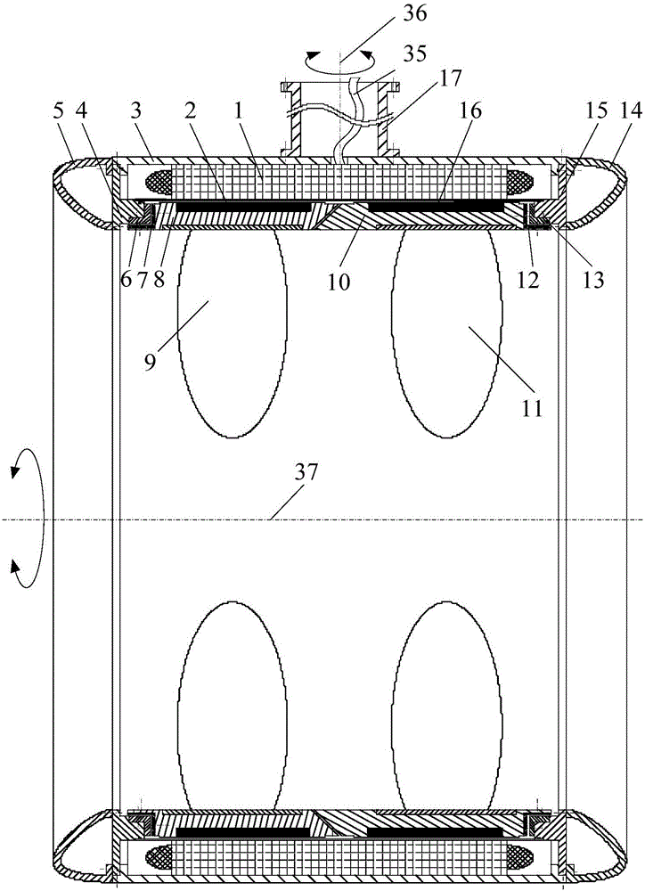
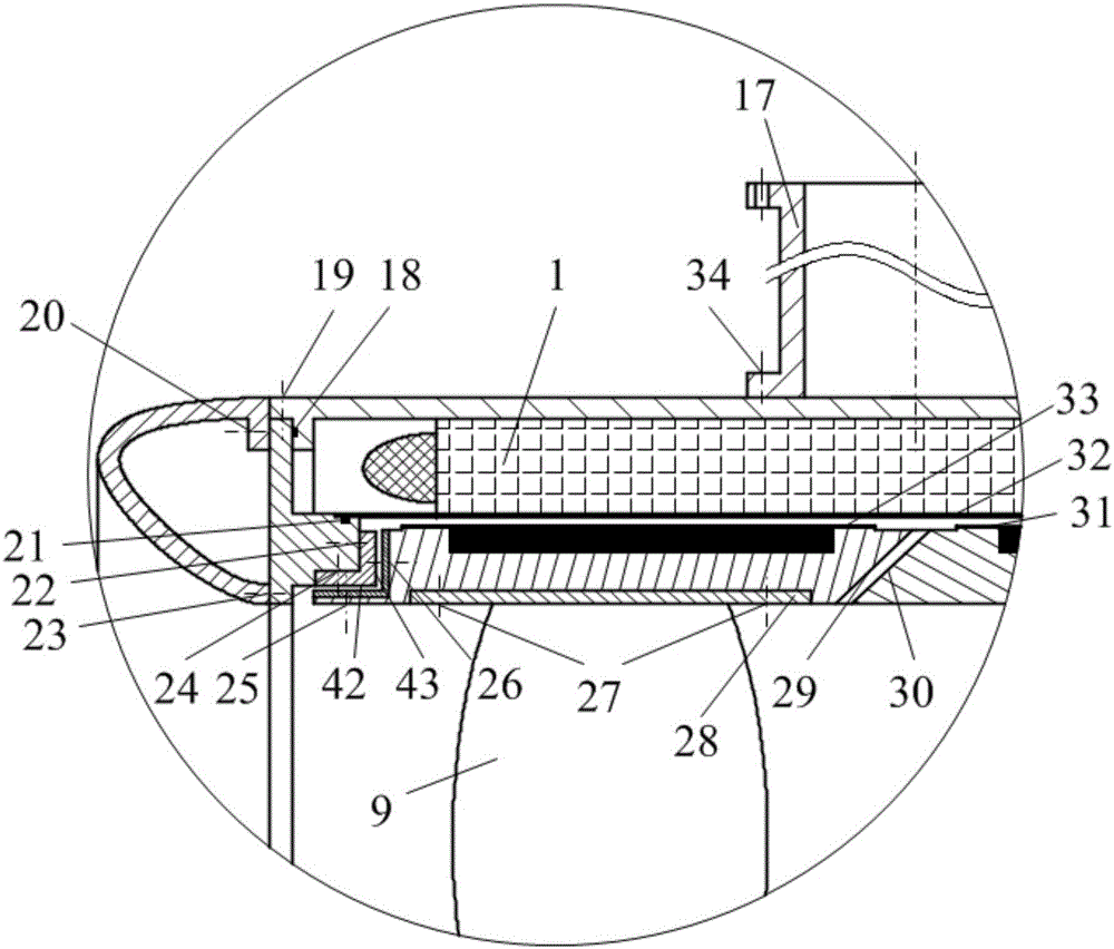
[0029] The counter-rotating shaftless wheel rim drive propeller provided by the invention has a structure such as figure 1 and figure 2 As shown, it consists of five parts: front rotor assembly, rear rotor assembly, conduit assembly, stator winding 1, and bearing assembly, wherein: the front rotor assembly and the rear rotor assembly are respectively installed in the inner cavity of the housing 3 of the conduit assembly, respectively It is supported by bearing assemblies installed at both ends of the conduit assembly; the stator winding 1 is installed in the inner wall of the casing 3 of the conduit assembly, and the inner wall of the stator winding 1 is opposite to the outer walls of the front rotor assembly and the rear rotor assembly; the conduit assembly is connected to the The hulls are connected.

[0030] The fr...


PUM


Abstract

The invention discloses an oppositely-rotating shaft-less rim-driven propeller which is provided with a guide tube component, wherein a stator winding, a front rotor component and a rear rotor component are arranged in the inner cavity of a shell; rotor rings in the two rotor components form a conical matching pair in an axial direction, and the polarities of permanent magnets embedded into the outer walls of the two rotor rings are opposite; and after the stator winding is electrified, the stator winding and the permanent magnets simultaneously form magnetic fields with opposite magnetic properties, namely that one stator drives two rotors to rotate to form a dual-rotor annular motor, thereby driving a front paddle and a rear paddle to rotate oppositely so as to generate thrust for pushing a ship to move forwards. The propeller disclosed by the invention has the advantages of small occupied space, high propulsion efficiency, large thrust, good transverse stability, small vibration and the like, and is particularly suitable for propelling of military boats and ships and modern civil ships as well as positioning of offshore platforms.

Description

technical field [0001] The invention belongs to the field of ship propulsion, in particular to a new type of propulsion with high efficiency, high thrust, good stability and high integration formed by simultaneously driving a hubless double rotor with blades to rotate counter-rotatingly by a single stator in a conduit propellers, so-called counter-rotating shaftless rim drive propellers. Background technique [0002] In recent years, with the needs of naval defense construction and the development of water trade, the performance requirements of ship propulsion devices have become higher and higher. The disadvantages of traditional shaft-driven propellers have gradually become prominent, and they can no longer better meet the work requirements. For example, the traditional shaft-driven propeller has many components, complex structure, large cabin space, large energy loss, difficult vibration and noise control, high construction and maintenance costs, etc. These defects have l...

Claims


Application Information

Patent Timeline
IPC IPC(8): B63H1/18H02K16/02
CPCB63H2005/1258B63H2001/165B63H1/16
Inventor 严新平欧阳武刘正林梁兴鑫
Owner WUHAN UNIV OF TECH
Learn More