
Tire locking brake for electric power construction transfer vehicle

A technology for electric power construction and transfer vehicles, which is applied to trolleys, motor vehicles, trolley accessories, etc., and can solve problems such as trolleys tilting, tires cannot be locked, and work tools are damaged

Active Publication Date: 2015-12-02
STATE GRID SHANDONG ELECTRIC POWER +2
View PDF4 Cites 5 Cited by
  • Summary
  • Abstract
  • Description
  • Claims
  • Application Information

AI Technical Summary

Problems solved by technology

[0002] During electric power construction, most of them need to work in the field, and they need to carry work tools during the work. Due to the complex terrain in the field, some places cannot enter the vehicle, and the work tools can only be brought to the work site by rotating the car. However, the transfer vehicles currently used are all It is a conventional push-pull trolley on the market. The tires in this trolley cannot be locked. When working in the field, it is affected by factors such as terrain and wind, and it is easy to cause the trolley to move by itself, which may cause the trolley to tip over and damage the work equipment. This is Weaknesses of existing technology

Method used


Image

  • Tire locking brake for electric power construction transfer vehicle

Examples


Embodiment Construction

[0015] In order to clearly illustrate the technical characteristics of this solution, the following will describe this solution through specific implementation modes and in conjunction with the accompanying drawings.

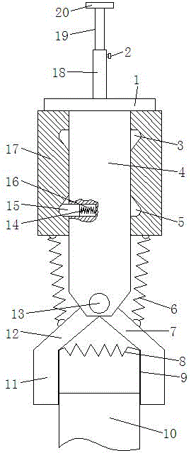
[0016] A wheel lock brake for electric construction transfer vehicles, as shown in the figure, it includes a fixed block 17 and a sliding shaft 4, the center of the fixed block 17 is provided with a through hole for the sliding shaft 4 to pass through, and the fixed block 17 The upper end of the sliding shaft 4 is fixedly connected with the driving plate 1, and the lower end is hinged with the clamping brackets 7 used in pairs. Preferably, the driving plate 1 and the sliding shaft 4 are welded and fixed. The upper end surface is fixed with a sleeve 18, the sleeve 18 is provided with a telescopic rod 19 that matches it, and the upper end of the sleeve 18 is provided with a locking knob 2 that cooperates with the telescopic rod 19, and the upper end of the telescop...


PUM


Abstract

The invention provides a tire locking brake for an electric power construction transfer vehicle. A fixed block and a sliding shaft of the tire locking brake are in clearance fit. The upper end of the sliding shaft is fixedly connected with a drive plate, and clamping supports used in pairs are hinged to the lower end of the sliding shaft. A sleeve is fixed to the upper end face of the drive plate, a telescopic rod with a handle is arranged in the sleeve, and a locking rotary knob is arranged at the upper end of the sleeve. A reset spring A is arranged between the two clamping supports, and reset springs B are connected between the two clamping supports and the lower end of the fixed block respectively. Upper limiting grooves and lower limiting grooves are sequentially formed in the side wall of a through hole in the vertical direction. At least two sets of upper limiting grooves and lower limiting grooves are evenly formed in the side wall of the through hole in the circumferential direction. A ball pin capable of matching the upper limiting grooves and the lower limiting grooves is arranged on the outer side wall of the sliding shaft, a radial mounting groove is formed in the outer side wall of the sliding shaft, and the ball pin is arranged in the radial mounting groove through a reset spring C. The brake can lock and unlock tires of the transfer vehicle.

Description

technical field [0001] The invention relates to an electric construction transfer vehicle, in particular to a wheel-locking brake for an electric construction transfer vehicle. Background technique [0002] During electric power construction, most of them need to work in the field, and they need to carry work tools during the work. Due to the complex terrain in the field, some places cannot enter the vehicle, and the work tools can only be brought to the work site by rotating the car. However, the transfer vehicles currently used are all It is a conventional push-pull trolley on the market. The tires in this trolley cannot be locked. When working in the field, it is affected by factors such as terrain and wind, and it is easy to cause the trolley to move by itself, which may cause the trolley to tip over and damage the work equipment. This is The deficiencies of existing technology. Contents of the invention [0003] The technical problem to be solved by the present inven...

Claims


Application Information

Patent Timeline
IPC IPC(8): B62B5/04
Inventor 刘玉恒王文宏杨晓峰滕兴强
Owner STATE GRID SHANDONG ELECTRIC POWER
Learn More