Magnetic separator

A magnetic separator and magnet technology, applied in the field of magnetic separators, can solve the problems of low magnetic separation efficiency, difficulty in controlling the feeding speed, and easy accumulation on the feeding board, so as to improve magnetic separation efficiency, facilitate equipment assembly, reduce The effect of miss rate

Inactive Publication Date: 2015-12-02
TIANJIN FUZHAO ALLOY MATERIAL
View PDF8 Cites 2 Cited by
  • Summary
  • Abstract
  • Description
  • Claims
  • Application Information

AI Technical Summary

Problems solved by technology

[0003] For complex tailings, polluted soil and industrial waste residues and other heavy metal-contaminated residues, multi-stage magnetic separators currently on the market generally use multi-magnetic rollers with different magnetic field strengths to be arranged in series in diagonal lines to achieve synchronous separation of multi-metal contaminated residues. operation, the structure of the magnetic separator is complex, and the feeding speed of the material after entering the magnetic separator is difficult to control, and it completely depends on the cutting board. The slurry tends to flow too fast during wet selection, and the material tends to accumulate on the cutting board during dry selection. , resulting in difficulty in full contact between the material and the magnetic roller, high leakage rate, and low magnetic separation efficiency. In addition, this type of magnetic separator generally adopts the feeding method of high-pressure water flow washing. In actual engineering applications, it is difficult to realize the recycling of water resources, resulting in Serious waste of water resources

Method used


Image

  • Magnetic separator
  • Magnetic separator

Examples


Embodiment Construction

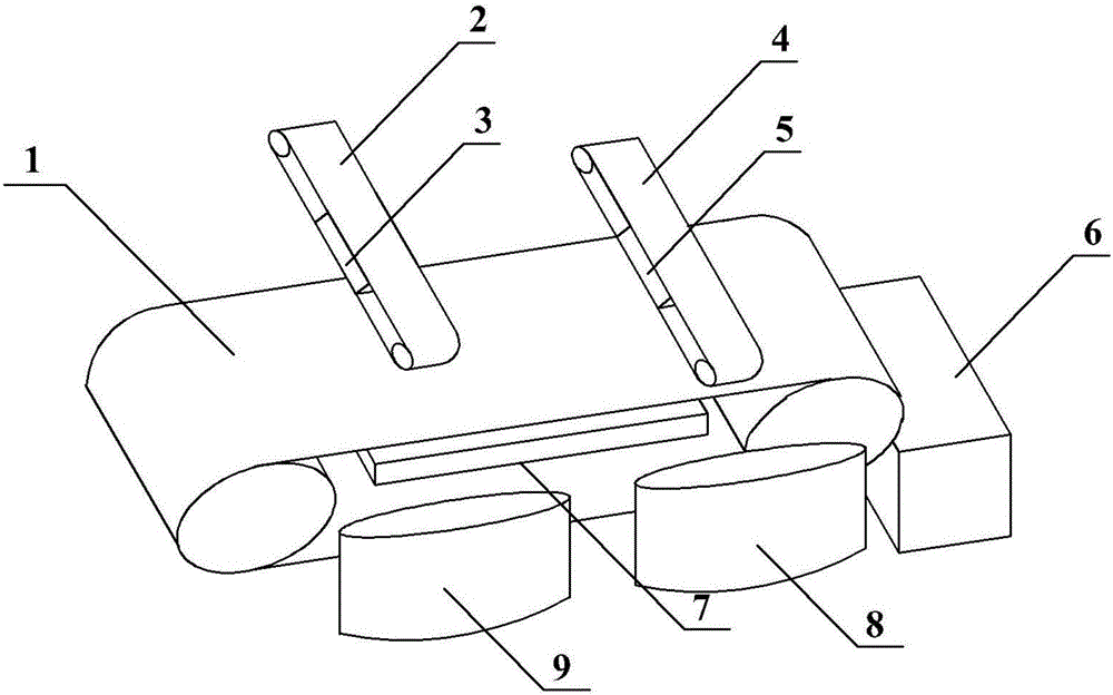
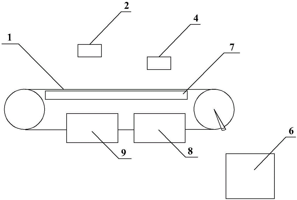
[0021] The magnetic separator of the present invention will be described in detail below in conjunction with the accompanying drawings.

[0022] Such as Figure 1-2 , a magnetic separator, the second roller conveyor belt 2 and the third roller conveyor belt 4 are spaced above the first roller conveyor belt 1 and the transmission direction of the second roller conveyor belt 2 and the third roller conveyor belt 4 is the same as that of the first roller conveyor belt 1 The conveying direction is vertical, and the lengthwise dimensions of the second roller conveyor belt 2 and the third roller conveyor belt 4 are larger than the width of the first roller conveyor belt 1 . The distance between the second roller conveyor belt 2 and the first roller conveyor belt 1 is greater than the distance between the third roller conveyor belt 4 and the first roller conveyor belt 1 . The first magnet 3 is fixed between the two rollers of the second roller conveyor belt 4 ; the second magnet 5 is...


PUM


Abstract

The invention discloses a multi-stage magnetic separator which comprises a first roller conveyor belt, a second roller conveyor belt, a third roller conveyor belt, a first magnet, a second magnet, a first collecting barrel, a second collecting barrel, a third collecting barrel, and an ultrasonic vibration plate. The multi-stage magnetic separator is simple in structure and high in magnetic separation efficiency. According to the magnetic separator, after powder enters the magnetic separator, the feeding speed does not rely on a feeding plate and can be completely adjusted through a motor; the powder and the magnet make full contact, so that the missing rate is effectively lowered, and the magnetic separation efficiency is improved. The magnetic separator is simple in structure, convenient to assemble and easy to maintain.

Description

technical field [0001] The invention relates to the field of permanent magnet powder preparation, in particular to a magnetic separator. Background technique [0002] Permanent magnet magnetic separator is a mechanical device that realizes separation according to the magnetic difference between materials. The basic principle is to use the background magnetic field generated by the permanent magnet and the magnetic field gradient force generated by the magnetic gathering medium to capture fine magnetic materials. It is widely used. One of the sorting processes with high versatility. In recent years, with the emergence of NdFeB permanent magnets with high magnetic energy level, the permanent magnet magnetic separation with the characteristics of compact and simple structure, low cost, low energy consumption, convenient operation and maintenance, and stable operation has been widely used. prospect. [0003] For complex tailings, polluted soil and industrial waste residues and...

Claims


Application Information

Patent Timeline
Patent Type & Authority Applications(China)
IPC IPC(8): B03C1/22
Inventor 张立军王少新孙晓东
Owner TIANJIN FUZHAO ALLOY MATERIAL
Why Eureka
Try Eureka