Junction box equipment

A junction box and equipment technology, applied in the direction of connection, conductive connection, clamping/spring connection, etc., can solve the problems that the state of the actuating element cannot be directly seen, high assembly costs, etc., and achieve reliable functions, simple structure, and fast installation Effect

Active Publication Date: 2017-12-26
PHOENIX CONTACT GMBH & CO KG
View PDF3 Cites 0 Cited by
  • Summary
  • Abstract
  • Description
  • Claims
  • Application Information

AI Technical Summary

Problems solved by technology

This system works, but has the disadvantage that the state of the individual actuating elements cannot be seen directly and, moreover, there is a high assembly outlay

Method used


Image

  • Junction box equipment
  • Junction box equipment
  • Junction box equipment

Examples


Embodiment Construction

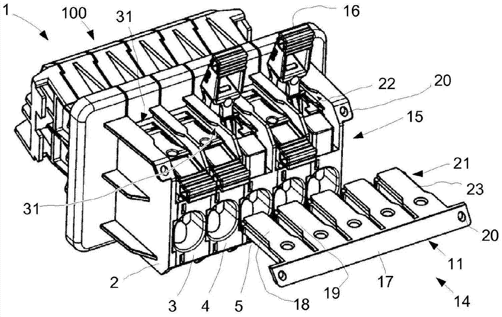
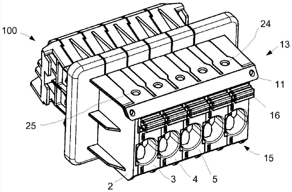
[0047] Reference attached Figures 1 to 8 An embodiment of the present invention is described in which, figure 1 A somewhat perspective view of a junction box 1 according to the invention is shown. Depicted next to the terminal box 1 is a locking device 11 which, together with the terminal box 1 , forms the terminal box arrangement 100 .

[0048] exist figure 1 In the open or unlocked position 14 shown in , the locking device 11 with the locking unit 18 is not guided into the corresponding locking receptacle 31 of the terminal box 1 . Thereby, the actuating lever 16 of the lever terminal 15 of the terminal box 1 can be shifted arbitrarily into the open position or the contact position. It is also possible that a single actuation lever 16 of the lever end 15 is opened, while the other actuation lever 16 remains closed.

[0049] The terminal box 1 has a housing 2 which can be designed as a common housing for all terminals 3 , 4 , 5 , etc. FIG. However, it is also possible f...


PUM


Abstract

A junction box device (100) comprising a junction box (1) having a housing (2) and a plurality of terminals (3, 4, 5). Each terminal (3, 4, 5) comprises a clamping unit (6) for contacting a conductor (7) receivable on the terminal (3, 4, 5) and a corresponding clamping unit (6) for An actuating unit (8) of the clamping unit (6) is moved in order to selectively move the clamping unit (6) between two positions (9, 10). One of said positions is the open position (9) and the other position is the contact position (10). A locking device (11) is provided. In the locking position (13), the locking device (11) prevents the actuation of the actuating unit (8) of a plurality of terminals together.

Description

technical field [0001] The invention relates to a junction box arrangement as well as a junction box and a locking device for such a junction box. Background technique [0002] Many different terminal boxes are known in the prior art, which have a plurality of terminals and which can be used for many different purposes. For example, junction boxes are known which are designed as wall bushing terminals and are suitable for connecting electrical lines for photovoltaic installations. In this case, and also in other cases, it is expedient to prevent actuation of the switch or of the lever end. In addition, corresponding securing elements or closures can be used to make undesired actuation more difficult or to prevent undetected actuation. [0003] In order to simultaneously protect a plurality of actuating elements against undesired and unauthorized actuation, a housing can be provided around all the elements, which blocks access to the actuating elements. Such a system works...

Claims


Application Information

Patent Timeline
Patent Type & Authority Patents(China)
IPC IPC(8): H01R4/48H01R9/24
CPCH01R9/24H01R4/48365H01R4/5008
Inventor J·梅斯塔尔斯
Owner PHOENIX CONTACT GMBH & CO KG
Why Eureka
Try Eureka