
Motor, stator core and stator punching

A technology of stator punching and stator core, applied to the static parts of the magnetic circuit, magnetic circuit shape/style/structure, etc., can solve the problems of limited number of winding turns, single stator core, low production efficiency, etc., to achieve Improve motor efficiency, avoid embedding wires, and improve production efficiency

Active Publication Date: 2018-09-07
ZHUHAI KAIBANG MOTOR MFR +4
View PDF6 Cites 0 Cited by
  • Summary
  • Abstract
  • Description
  • Claims
  • Application Information

AI Technical Summary

Problems solved by technology

[0004] However, since the winding method of the stator core is a single cross-slot embedded wire, that is, the winding spans a certain winding slot and is wound on the inner teeth
The cross-slot embedding process of winding wires is complicated, and must go through processes such as winding, embedding, binding, shaping, and dipping. The production process is cumbersome and the production efficiency is low; moreover, the number of winding turns is limited, which affects the efficiency of the motor

Method used


Image

  • Motor, stator core and stator punching
  • Motor, stator core and stator punching
  • Motor, stator core and stator punching

Examples


Embodiment Construction

[0035] The core of the invention is to provide a stator stamping to improve production efficiency and motor efficiency. The present invention also provides a stator iron core and a motor with the above-mentioned stator punch.

[0036] In order to enable those skilled in the art to better understand the solution of the present invention, the present invention will be further described in detail below in conjunction with the accompanying drawings and specific embodiments.

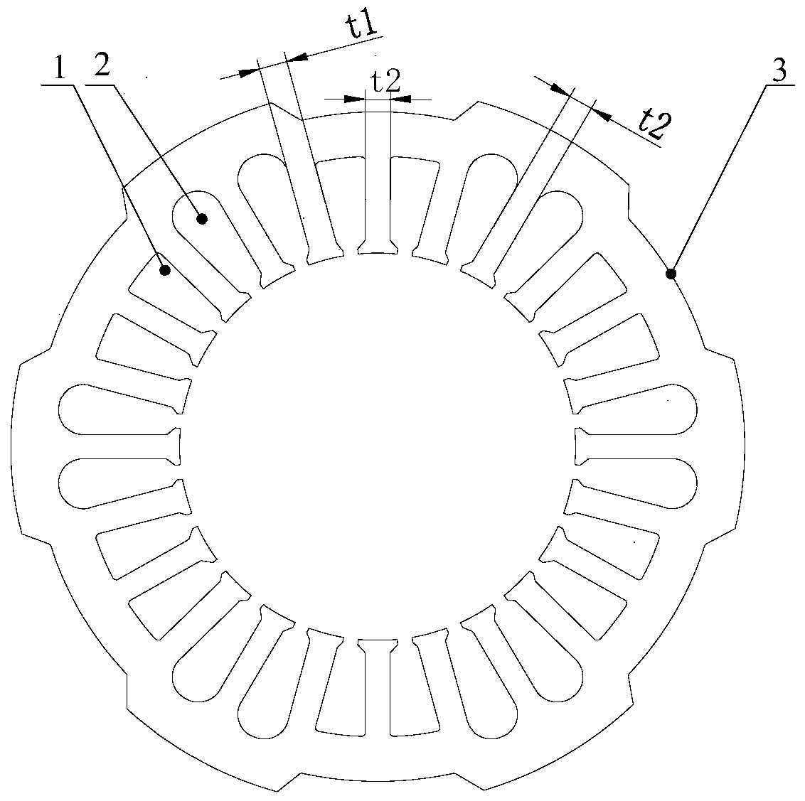
[0037] Please refer to figure 2 , figure 2 A schematic diagram of the first structure of the stator punch provided by the present invention.

[0038] In this specific embodiment, the stator punch includes a second winding slot 2 and a first winding slot 1, the second winding slot 2 is used to wind the winding wire between the inner slots of the stator punch, and the first winding slot 1 is used for Winding wire for winding the yoke of the stator punching. Wherein, the depth of the second winding slot 2 ...


PUM


Abstract

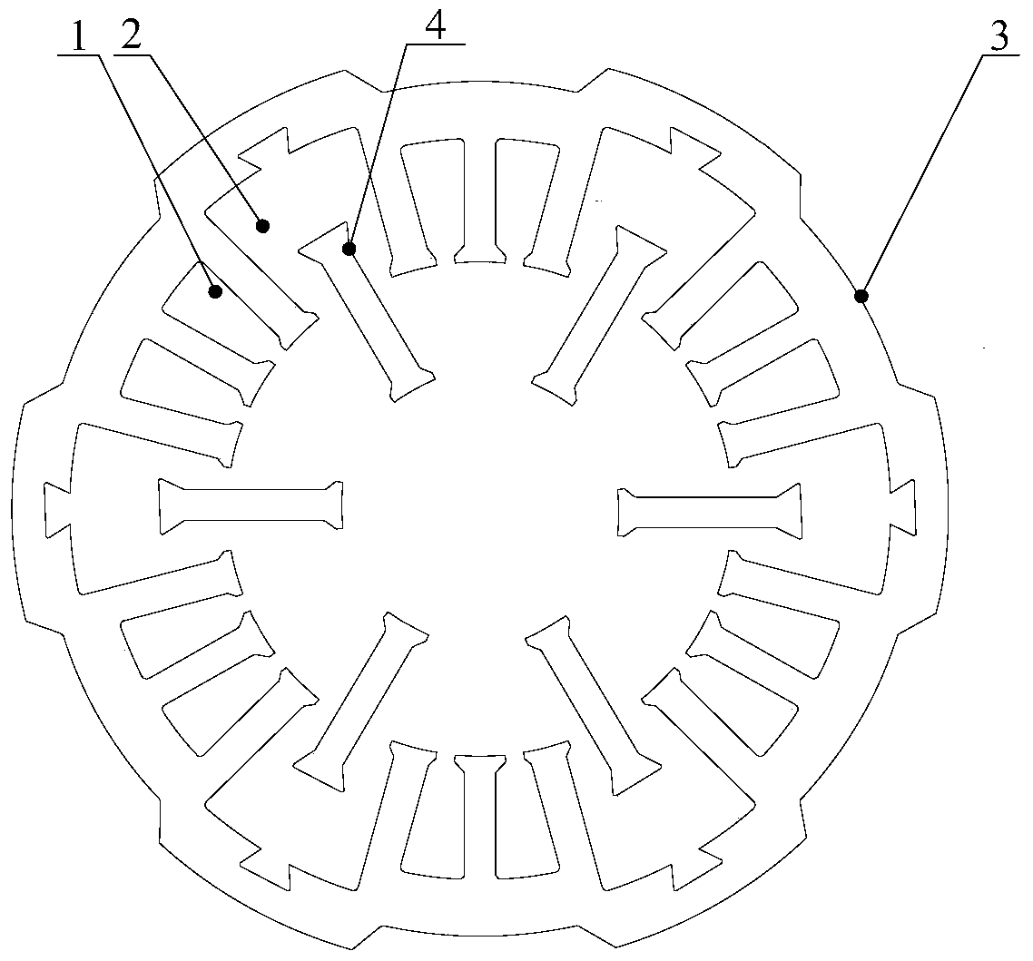
The invention discloses a motor, a stator core and a stator blade thereof. The stator blade comprises second winding grooves (2) for winding a winding wire between inner troughs of the stator blade, and first winding grooves (1) for winding a winding wire of a yoke part of the stator blade. The depth of the second winding groove (2) is greater than that of the first winding groove (1). At least two second winding grooves (2) fall into a group, and at least one first winding groove (1) falls into a group. The second winding groove groups and the first winding groove groups are arranged at intervals. Due to use of the winding manner, operations of inserting line, binding line and dipping paint are prevented, and the production efficiency is improved effectively; as the depth of the second winding groove is greater than that of the first winding groove, the primary winding wound on the yoke part of the first winding groove does not block the second winding groove, and the number of turns of winding of the second winding groove is not limited and can be more, so that the motor efficiency is improved.

Description

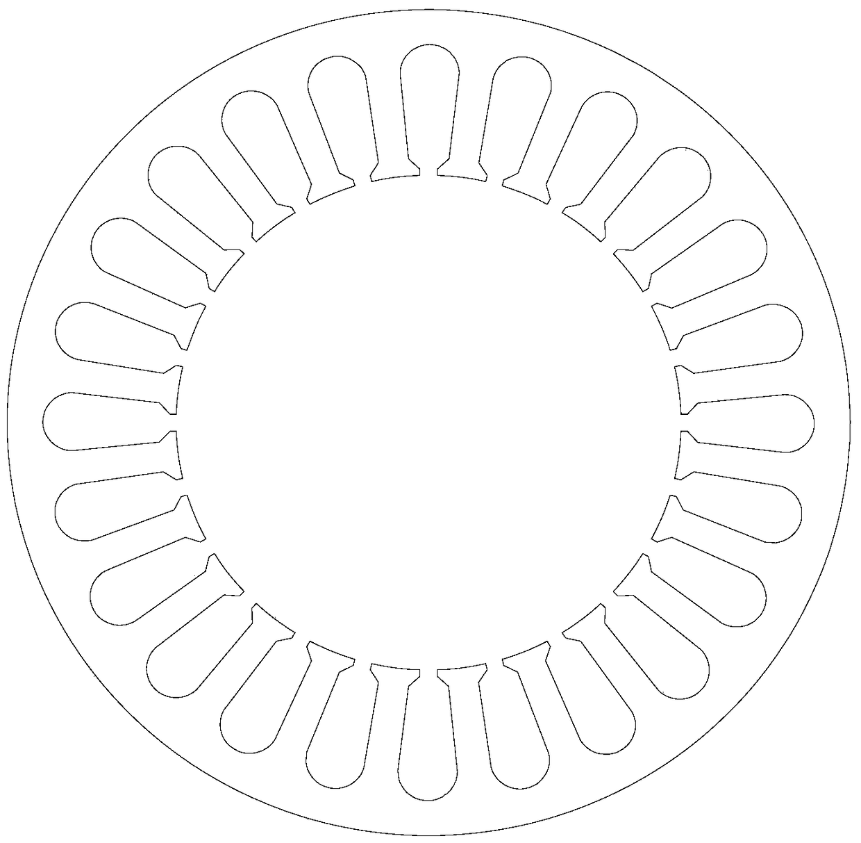
technical field [0001] The invention relates to the technical field of motor equipment, in particular to a motor, a stator core and a stator punch. Background technique [0002] The stator core of the motor is formed by stacking stator punches, and the inner slots of the superimposed stator punches are all aligned. [0003] At present, the stator core is usually a full-circle stator, and the stator punches are also circular. Such as figure 1 As shown, a plurality of internal teeth are arranged inside the stator punch, and two adjacent inner teeth form winding slots for winding winding wires, and the multiple winding slots on the stator punch have the same size and groove shape. [0004] However, since the winding method of the stator core is a single cross-slot embedded wire, that is, the winding straddles a certain winding slot and is wound on the inner teeth. The process of inserting winding wires across slots is complicated, and must go through processes such as windin...

Claims


Application Information

Patent Timeline
Patent Type & Authority Patents(China)
IPC IPC(8): H02K1/16
Inventor 漆凌君
Owner ZHUHAI KAIBANG MOTOR MFR
Learn More