
Transmitter and monitoring system thereof

A technology for monitoring systems and transmitters, applied in the field of monitoring systems, can solve the problems of multiplied cost, non-reusable, difficult mass production, etc.

Active Publication Date: 2015-11-25
DELTA ELECTRONICS SHANGHAI CO LTD
View PDF6 Cites 0 Cited by
  • Summary
  • Abstract
  • Description
  • Claims
  • Application Information

AI Technical Summary

Problems solved by technology

This cost grows exponentially as the number of sensors increases
[0006] 2. The production cost of the transmitter is high
In this way, in order to share the cost, it is difficult to reduce the selling price of a single transmitter, and it is difficult to carry out mass production
[0007] 3. Waste of power and short system life
The transmitter has a low number of processing channels and cannot be reused. Moreover, each transmitter must be in a working state even when no data is needed, which not only wastes power, but also shortens the life of the system.
Usually a monitoring system is equipped with many kinds of sensors. Under the condition of slow data collection, for example, in the normal system with a collection interval of more than ten minutes, or even one or two hours or one day, this waste of power and short system life The phenomenon is particularly serious

Method used


Image

  • Transmitter and monitoring system thereof
  • Transmitter and monitoring system thereof
  • Transmitter and monitoring system thereof

Examples


Embodiment Construction

[0041] In order to solve at least part of the above-mentioned problems existing in the prior art, the present application proposes an intelligent transmitter and a monitoring system using the transmitter. The intelligent transmitter proposed in this application and the monitoring system using the transmitter are especially suitable for low-frequency continuous acquisition sensors.

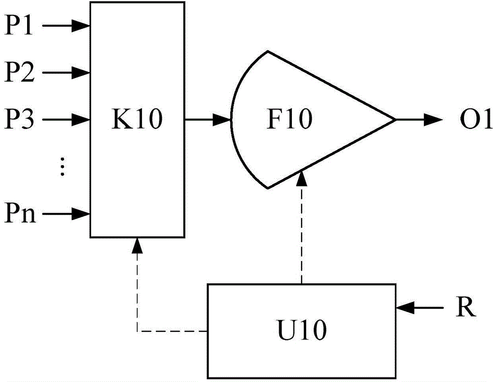
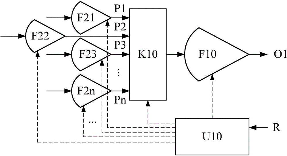
[0042] The following will combine Figure 2 to Figure 13 Describe the present application in detail, wherein, the same reference numerals represent the same or similar equipment or signals, the solid lines and their arrows represent the transmission direction of signals or data and the coupling relationship between related components, and the dotted lines and their arrows represent the control relationship, An ellipsis indicates that a plurality of similar structures or components are omitted.

[0043] figure 2 It is a schematic diagram schematically illustrating the block diagram of an embodime...


PUM


Abstract

The present disclosure discloses a transmitter and a monitoring system using this transmitter, the transmitter includes: a multi-to-one multiplexing switch configured to receive a plurality of sensor signals of a plurality of channels through a plurality of input terminals, select one sensor signal from the plurality of sensor signals, and output the selected sensor signal through a output terminal; a first variable gain amplifier configured to receive the selected sensor signal, amplify the selected sensor signal with a gain within a first gain range, and output the amplified sensor signal; a control parameter input terminal configured to receive an input control parameter from outside of the transmitter; and an operating and switching selector configured to perform operations according to the input control parameter, so as to control the multi-to-one multiplexing switch to select the one sensor signal and control the gain of the first variable gain amplifier.

Description

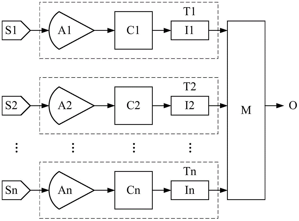
technical field [0001] The present application relates to a transmitter and a monitoring system using the transmitter. Background technique [0002] With the popularization and industrialization of IoT technology, the usage of sensors has increased tremendously. Usually, the analog signal of the sensor needs to be sent through the transmitter for further processing. Therefore, the demand and functional requirements for the transmitter are increasing. [0003] figure 1 It is a schematic diagram schematically illustrating a typical topology of sensors and transmitters in the prior art, and the connection relationship of each component contained therein is as follows figure 1 shown in . like figure 1 As shown in , the transmitters T1, T2, ... Tn in the prior art represented by the dotted line box need to provide corresponding different and uncommon amplifiers A1, A2, ... An according to different types of sensors S1, S2, ... Sn respectively Amplify the signal, perform anal...

Claims


Application Information

Patent Timeline
IPC IPC(8): G05B19/048
CPCH04J3/14H04J7/00H04L5/04H04L29/08G01D3/02G01D3/028G01D21/00H04L67/12G05B19/048
Inventor 朱子玉翟大忠
Owner DELTA ELECTRONICS SHANGHAI CO LTD
Learn More