
Mask plate, array substrate and manufacturing method of array substrate

A technology of array substrate and mask plate, which is applied in the field of liquid crystal display, can solve problems such as erosion and scratches in the terminal area, and achieve the effect of ensuring reliability

Active Publication Date: 2015-11-25
WUHAN CHINA STAR OPTOELECTRONICS TECH CO LTD
View PDF9 Cites 2 Cited by
  • Summary
  • Abstract
  • Description
  • Claims
  • Application Information

AI Technical Summary

Problems solved by technology

[0005] The technical problem to be solved by the present invention is to solve the problem that the terminal area of ​​the existing array substrate is corroded or scratched by water vapor due to the terminal area being suspended

Method used


Image

  • Mask plate, array substrate and manufacturing method of array substrate
  • Mask plate, array substrate and manufacturing method of array substrate
  • Mask plate, array substrate and manufacturing method of array substrate

Examples


Embodiment Construction

[0044] The implementation of the present invention will be described in detail below in conjunction with the accompanying drawings and examples, so as to fully understand and implement the process of how to apply technical means to solve technical problems and achieve technical effects in the present invention. It should be noted that, as long as there is no conflict, each embodiment and each feature in each embodiment of the present invention can be combined with each other, and the formed technical solutions are all within the protection scope of the present invention.

[0045] Also, in the following description, for purposes of explanation, numerous specific details are set forth in order to provide a thorough understanding of embodiments of the invention. It will be apparent, however, to one skilled in the art that the present invention may be practiced without the specific details or in the particular manner described.

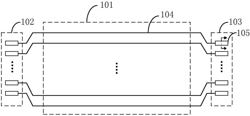
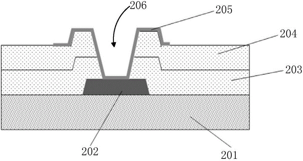
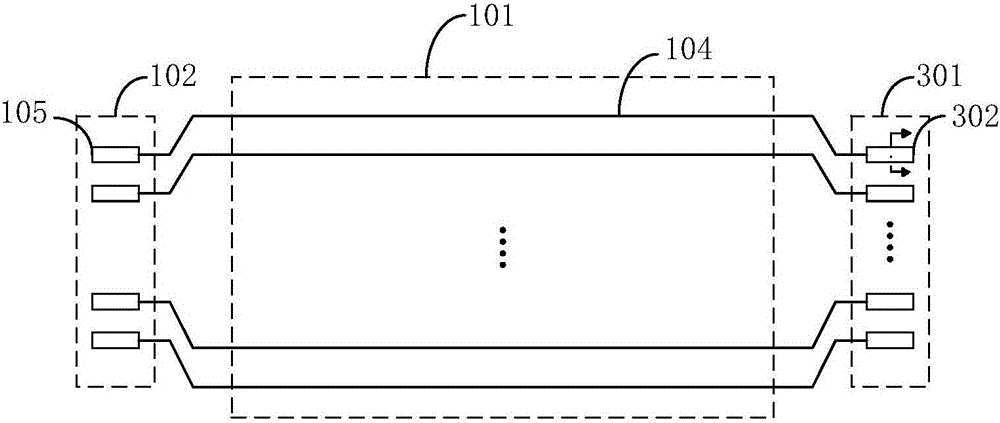
[0046] figure 1 A schematic structural diagram of ...


PUM


Abstract

The invention discloses a mask plate, an array substrate and a manufacturing method of the array substrate. The mask plate comprises a first patterned light-transmitting region formed on one side of the mask plate, a second patterned light-transmitting region formed inside the mask plate and located on the opposite side of the first patterned light-transmitting region, a first mark and a second mark, wherein the first mark is formed on the side, close to the center of the mask plate, of the first patterned light-transmitting region, and a first preset distance is formed between the first mark and the first patterned light-transmitting region; the second mark is formed on the side, away from the center of the mask plate, of the first patterned light-transmitting region, and a second preset distance is formed between the second mark and the first patterned light-transmitting region. When one connecting terminal area in the array substrate made from the mask plate is suspended, a gate line is covered with an insulating layer, in this way, the gate line is not likely to be corroded by vapor in air or scratched, and then reliability of the array substrate is guaranteed.

Description

technical field [0001] The present invention relates to the field of liquid crystal display technology, in particular to a mask plate, an array substrate and a manufacturing method thereof. Background technique [0002] Liquid crystal displays have the advantages of low radiation, small size, and low energy consumption. They have gradually replaced traditional cathode ray tube displays and are widely used in products such as flat-screen TVs, personal computers, and mobile display panels. [0003] For a large-size liquid crystal display panel, due to the long wiring of the array substrate, the RC time delay of the line and the large line load, it is generally necessary to use a double-sided driving method for driving. However, for the same product, in order to meet the needs of different customers, the driving methods of the liquid crystal display panel (such as signal inversion method and frame refresh rate, etc.) will be different, so different driving methods can correspon...

Claims


Application Information

Patent Timeline
Patent Type & Authority Applications(China)
IPC IPC(8): G02F1/1362H01L27/12H01L21/77
CPCG02F1/136286G02F1/136295H01L27/1248H01L27/1288
Inventor 徐向阳张正义
Owner WUHAN CHINA STAR OPTOELECTRONICS TECH CO LTD
Learn More