
Focusing hole plate flowmeter and using method thereof

An orifice flowmeter and orifice flow technology, which is applied in the direction of volume measurement, liquid/fluid solid measurement, volume/mass flow generated by mechanical effects, etc. narrower than other issues

Active Publication Date: 2015-11-25
LIAONING FOCUS TECH
View PDF5 Cites 10 Cited by
  • Summary
  • Abstract
  • Description
  • Claims
  • Application Information

AI Technical Summary

Problems solved by technology

Moisture passing through the differential pressure flowmeter will produce a false high phenomenon, which has always seriously affected the measurement accuracy of the orifice flowmeter
[0007] Therefore, how to solve a series of problems such as the narrow turndown ratio of the standard orifice plate flowmeter, the bluntness of the sharp corner of the orifice plate, the deposition upstream of the orifice plate, and the false height of the moisture measurement is a key point.

Method used


Image

  • Focusing hole plate flowmeter and using method thereof

Examples


Embodiment Construction

[0026] The specific embodiment of the present invention is further described below in conjunction with accompanying drawing:

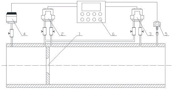
[0027] Such as figure 1 As shown, a focused orifice flowmeter includes an orifice plate 1; a front-end differential pressure transmitter 2, the front-end differential pressure transmitter 2 is installed on the front end of the orifice plate 1, and the differential pressure value before and after the orifice plate 1 is measured (according to Depending on the position of pressure taking, it can be divided into corner joint pressure taking, flange pressure taking, D-D / 2 pressure taking); the rear end differential pressure transmitter 3, the rear end differential pressure transmitter 3 is installed on the orifice plate 1 The rear end measures the pressure loss value of the measured medium after passing through the orifice plate 1; the pressure transmitter 4 is installed on the front end of the orifice plate 1 to measure the pressure value at the front end ...


PUM


Abstract

The invention relates to a focusing hole plate flowmeter, which comprises a hole plate, a front differential pressure transmitter, a rear differential pressure transmitter, a pressure transmitter, a temperature sensor and an on-line flow calculator, wherein the front differential pressure transmitter is arranged on the front end of the hole plate, and measures front and rear differential pressure, the rear differential pressure transmitter is arranged on the rear end of the hole plate, and measures pressure loss value of measured medium after the measured medium passes through the hole plate, the pressure transmitter is arranged on the front end of the hole plate, and measures a pressure value on the front end of the hole plate, the temperature sensor is arranged on the rear end of the hole plate, and the on-line flow calculator is respectively connected with the front differential pressure transmitter, the rear differential pressure transmitter, the pressure transmitter and the temperature sensor. Compared with the prior art, the focusing hole plate flowmeter has the beneficial effects that the focusing hole plate flowmeter can automatically adjust meter factors by adding a pressure measuring point on the rear segment of the hole plate, measuring pressure loss of measured medium and then comparing with a differential pressure value and calculating the change of a differential pressure radio on line.

Description

technical field [0001] The invention relates to the technical field of flow measurement, in particular to a focusing orifice flowmeter and a use method thereof. Background technique [0002] The standard orifice flowmeter is widely used. It is a standard throttling device and needs to be designed, manufactured, installed and used in accordance with the national standard GB / T2624-2006. The standard orifice flowmeter has the advantages of simple structure, good durability, no need for real flow calibration, high degree of standardization and high accuracy, and is widely used in industrial production. The measurement characteristics of the orifice flowmeter depend on the geometric characteristics of the device, and the flow rate has a definite relationship with the differential pressure. [0003] The traditional method regards all variables other than differential pressure as constants, and finally only determines the flow rate by measuring the differential pressure. In this ...

Claims


Application Information

Patent Timeline
Patent Type & Authority Applications(China)
IPC IPC(8): G01F1/42G01F15/04
Inventor 贾会安
Owner LIAONING FOCUS TECH
Learn More