
Wiring duct cutting marking-off ruler

A technology for marking rulers and wire slots, which is applied in the field of measuring tools and can solve problems such as troublesome operation and low work efficiency

Inactive Publication Date: 2015-11-25
杨夕志
View PDF7 Cites 1 Cited by
  • Summary
  • Abstract
  • Description
  • Claims
  • Application Information

AI Technical Summary

Problems solved by technology

[0003] In order to overcome the disadvantages of troublesome operation and low work efficiency in the prior art of using a ruler as a marking tool, the present invention provides a wire trough cutting and marking tool with simple structure, high marking precision, convenient operation and high work efficiency. ruler

Method used


Image

  • Wiring duct cutting marking-off ruler
  • Wiring duct cutting marking-off ruler
  • Wiring duct cutting marking-off ruler

Examples


Embodiment Construction

[0014] exist figure 2 Among them, a wire trough cutting ruler, which includes a rectangular measuring ruler body 1 .

[0015] Such as figure 2 As shown, a length marking line 2 is provided on one side of the measuring ruler body 1 along the length direction. For the convenience of measurement, in this embodiment, the first and last scoring lines of the length marking line 2 coincide with both sides of the measuring ruler body.

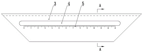
[0016] exist figure 1 Among them, a wire trough cutting marking ruler, which also includes a marking ruler body 3.

[0017] Such as image 3 As shown, one side of the marking ruler body 3 along the length direction is vertically connected with the other side ruler edge of the measuring ruler body 1 in the same direction to form a right-angle corner ruler.

[0018] exist figure 1 Among them, the ruler edges on both sides of the marking ruler body 3 along the width direction are respectively inwardly inclined at an angle of 45° symmetrically.

...


PUM


Abstract

The invention discloses a wiring duct cutting marking-off ruler and mainly aims to solve problems of operation difficulty and low work efficiency existing in the prior art when straight rulers are taken as marking-off tools. The wiring duct cutting marking-off ruler comprises a rectangular measuring ruler body, wherein a ruler edge at one side along the length direction of the measuring ruler body is provided with a length identification line. The wiring duct cutting marking-off ruler is characterized by further comprising a marking-off ruler body, the ruler edge at one side of the marking-off ruler body along the length direction and a ruler edge on another side of the measuring ruler body are vertically connected to form a right-angle angle ruler, and two ruler edges at two sides of the marking-off ruler body along the width direction symmetrically incline 45 DEG inwards respectively. The wiring duct cutting marking-off ruler has advantages of simple structure, high marking-off precision, convenient use and high work efficiency.

Description

technical field [0001] The invention relates to a measuring tool characterized by using a mechanical measuring method, in particular to a ruler for cutting and marking wire grooves. Background technique [0002] We know that in circuit management, it is necessary to centrally install control components, monitoring components, etc., in order to control lines and collect data. The distribution board is to regularly fix the relevant components on the distribution board, and realize the circuit function through wire connection. In the process of plate distribution, an open-slot type wire trough is generally used to standardize the direction of the wire. The open-slot type wire trough is composed of a fixed bottom and sides vertically located on both sides of the fixed bottom. There are inlet and outlet slots on the top, and the wire slots are framed and fixed on the distribution board around the relevant components. Therefore, the connecting ends of two adjacent wire slots must...

Claims


Application Information

Patent Timeline
IPC IPC(8): G01B3/04G01B3/56
Inventor 杨夕志
Owner 杨夕志
Learn More