
Device for recovering reclaimed water

A technology for reclaimed water and water retention, which is applied to water supply devices, valve operation/release devices, valve devices, etc., can solve problems such as inconvenient maintenance, increased production difficulty, and increased production costs.

Inactive Publication Date: 2015-11-25
杨文斌
View PDF1 Cites 2 Cited by
  • Summary
  • Abstract
  • Description
  • Claims
  • Application Information

AI Technical Summary

Problems solved by technology

The control valve has many parts and complex structure, including a tee pipe and a valve body, and the valve body includes a pipe body, a cover body and a pull rope; The function of the through pipe, so it has higher requirements for the sealing process; the pipe body and the cover body of the valve body need to be hinged together through hinges; the above three factors increase the difficulty of production, increase the production cost, and cause inconvenient maintenance
In order to automatically prevent the reservoir from overflowing, the right outlet of the control valve is connected to the lower part of the reservoir through a pipe; the pull rope enters the reservoir through the pipe, and the end is connected to a floating ball; rope, so that the cover closes the right outlet, opens the lower outlet, and the excess water flows into the sewer; the connection between the control valve and the reservoir makes the recovered water have to be poured from the reservoir into other containers before it can be moved and used, resulting in inconvenient use

Method used


Image

  • Device for recovering reclaimed water
  • Device for recovering reclaimed water
  • Device for recovering reclaimed water

Examples


Embodiment Construction

[0013] The specific implementation manners of the present invention will be described in detail below in conjunction with the accompanying drawings.

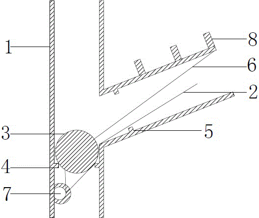
[0014] like figure 1 and figure 2 As shown, the device for reclaimed water includes a three-way pipe 1, a pull rope 2 and a spherical obstruction 3; the three-way pipe 1 includes a water inlet connected to a sink of utensils such as a washbasin at the upper end, and a water inlet at the lower end. The sewer end connected to the sewer and the horizontal water retention end inclined upward to form a certain angle with the horizontal plane; the sewer end has a narrow portion 4 that prevents the spherical obstruction 3 from passing through, and the water retention end has a narrow portion 5 that prevents the spherical obstruction 3 from passing through The narrow part 4 and the narrow part 5 are annular protrusions on the inner wall of the three-way pipe 1; the spherical obstruction 3 is located in the three-way pipe 1 and can mov...


PUM


Abstract

The invention provides a device for recovering reclaimed water, wherein the device is simple, low in price and practical. The device comprises a three-way pipe 1, a digging rope 2 and a blocking object 3. The three-way pipe 1 comprises a water inlet end, a water outlet end and a water leaving end. The water outlet end is provided with a narrow portion 4, and the water leaving end is provided with a narrow portion 5. The blocking object 3 is located in the three-way pipe 1 and can freely move between the narrow portion 4 and the narrow portion 5 but cannot pass beyond. One end of the digging rope 2 is connected to the blocking object 3, and the other end of the digging rope 2 penetrates out of the water leaving end. An elastic retraction component 6 can be additionally arranged, pull the blocking object 3 towards and enable the blocking object 3 to abut against the narrow portion 5 of the water leaving end. A hole 7 is additionally formed, and the digging rope 2 penetrates through the hole 7, returns and then penetrates out of the water leaving end. A falling object 9 can be then additionally arranged, pull the blocking object 3 towards and enable the blocking object 3 to abut against the narrow portion 4 of the water outlet end. Through movement of the blocking object 3 between the narrow portion 4 and the narrow portion 5, recovery of reclaimed water is achieved, and water resource is saved.

Description

technical field [0001] The invention relates to a device for recovering reclaimed water, in particular to a device for reclaiming reclaimed water comprising a three-way pipe. Background technique [0002] In daily life, the clean water that flows out of the water pipe is called upper water; the sewage that flows into the sewer is called sewer water; the water that flows out of the water pipe and has not yet flowed into the sewer is called middle water. Although part of the reclaimed water has been used, it is relatively clean and can be reused; for example, the washing water in the washbasin can be used to mop the floor and flush the toilet. This part of reclaimed water is often directly discharged into the sewer, if it can be recycled, it can save a lot of water resources. The authorization announcement number is CN202925632U, and the authorization announcement date is May 08, 2013. The utility model patent authorization announcement named "Slap Door Type Automatic Water-s...

Claims


Application Information

Patent Timeline
IPC IPC(8): F16K11/056F16K27/02F16K31/20E03C1/122
CPCF16K11/056E03C1/122F16K27/0245F16K27/0263F16K31/20
Inventor 杨文斌
Owner 杨文斌
Learn More