


Quick Research
Generate reliable direction feasibility study reports for your R&D in just a few steps.

Technical Q&A
Discover and master advanced knowledge NOW. Basics, ideas, possibilities, all at once.

Find Solutions
As an expert in R&D theories, this can generate solutions to your technical problems instantly.

Evaluate Feasibility
Analyze your overall solution with one click, know your potential R&D risks in advance.

Monitor Landscape
Get weekly tech updates, stay abreast of the latest tech innovations and key insights.
A sealless lng submersible pump
A sealless, submersible pump technology, applied in the direction of pumps, pump devices, pump components, etc., can solve the problems of long time, inability to refill the submersible pump, and inexhaustible unloading, etc. Anti-cavitation performance, the effect of reducing requirements
- Summary
- Abstract
- Description
- Claims
- Application Information
AI Technical Summary
Problems solved by technology
Method used
Image

Examples
Embodiment 1
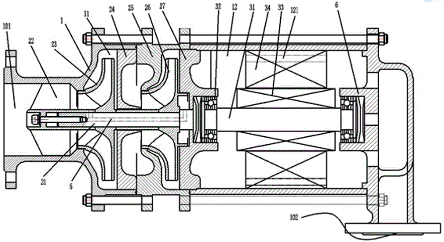
[0020] A kind of sealless LNG submersible pump, as attached figure 1 As shown, it includes a casing 1 forming a first cavity 11 and a second cavity 12, a pump main body set in the first cavity 11 through a pump main shaft, and a low temperature bearing 32 set in the second cavity 12. Drive motor; the second cavity 12 is located above the first cavity 11, the housing 1 has a liquid inlet 101 below the first cavity 11, and a liquid outlet 102 above the second cavity 12, LNG It is output from the liquid inlet 101 through the first cavity 11 and the second cavity 12 to the liquid outlet. The functional parts arranged along the pump main shaft 21, from the liquid inlet 101 to the liquid outlet 102, sequentially include the inducer 22, the first impeller 23, the first guide vane 24, the secondary housing 25, the secondary impeller 26, and the secondary guide vane 27 , the driving shaft 31 of the driving motor is arranged coaxially with the pump main shaft 21, and the secondary guid...
Embodiment 2
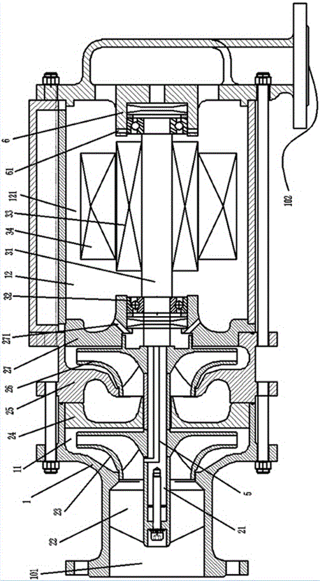
[0022] A kind of sealless LNG submersible pump, as attached figure 2 As shown, it includes a casing 1 forming a first cavity 11 and a second cavity 12, a pump main body set in the first cavity 11 through a pump main shaft, and a low temperature bearing 32 set in the second cavity 12. Drive motor; the second cavity 12 is located above the first cavity 11, the housing 1 has a liquid inlet 101 below the first cavity 11, and a liquid outlet 102 above the second cavity 12, LNG It is output from the liquid inlet 101 through the first cavity 11 and the second cavity 12 to the liquid outlet. The functional parts arranged along the pump main shaft 21, from the liquid inlet 101 to the liquid outlet 102, sequentially include the inducer 22, the first impeller 23, the first guide vane 24, the secondary housing 25, the secondary impeller 26, and the secondary guide vane 27 , the driving shaft 31 of the driving motor is arranged coaxially with the pump main shaft 21, and the secondary gui...
PUM
 Abstract
Description
Claims
Application Information
 - R&D Engineer
- R&D Manager
- IP Professional
- Industry Leading Data Capabilities
- Powerful AI technology
- Patent DNA Extraction
Browse by: Latest US Patents, China's latest patents, Technical Efficacy Thesaurus, Application Domain, Technology Topic, Popular Technical Reports.
© 2024 PatSnap. All rights reserved.Legal|Privacy policy|Modern Slavery Act Transparency Statement|Sitemap|About US| Contact US: help@patsnap.com