Device and method for nested layered injection of isotopic tracer
An isotope tracer and injection device technology, which is applied in the field of isotope tracer nested layered injection device, can solve the problem of increasing the contradiction between layers in oil fields, the inability to accurately control the injection amount of isotope tracer, and the inability of isotope tracer Accurate monitoring and other issues to achieve the effect of accurate monitoring
- Summary
- Abstract
- Description
- Claims
- Application Information
AI Technical Summary
Problems solved by technology
Method used
Image


Examples
Embodiment 1
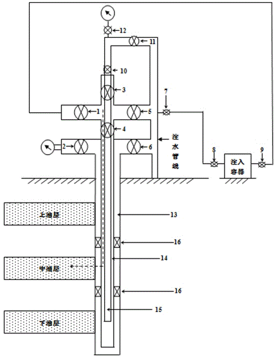
[0033] according to figure 1 As shown, the nested layered injection device of the present invention includes an injection container, one end of the injection container is connected to a water injection pipeline through a valve 8 and a four-point high pressure valve 7 in turn, and the other end of the injection container is connected to the valve 9, the layered injection device is provided with valve 12, valve 11, valve 10, valve 3, valve 1, valve 5, valve 4, valve 2, and valve 6 from top to bottom, and the layered injection device is also It includes a casing 13, an oil pipe 14 is sleeved inside the casing 13, a center pipe 15 is sleeved inside the oil pipe 14, and the casing 13, the oil pipe 14 and the center pipe 15 communicate with the water injection pipeline respectively, and the The casing 13 communicates with the upper oil layer, the oil pipe 14 communicates with the middle oil layer, and the central pipe 15 communicates with the lower oil layer, and the underground par...
Embodiment 2
[0035] according to figure 2 As shown, tritium water is injected into the upper oil layer, and the specific steps are as follows:
[0036] a. Connect valve 9 to valve 2;
[0037] b. Close valve 2 and valve 6, open valve 7, valve 8, and valve 9, pressurize to 35Mpa, and test the pressure without leakage;
[0038] c. Close the valve 7, and slowly inject tritium water into the layered injection device after the process pressure in the pipe is removed;
[0039] d. Open valve 2 and valve 7, and clear water will be brought into the upper oil layer corresponding to the casing through valve 7, valve 8, valve 9 and valve 2.
Embodiment 3
[0041] according to image 3 As shown, injecting into the upper oil layer 35 S-sodium sulfate aqueous solution, concrete steps are as follows:
[0042] a. Connect valve 9 to valve 1;
[0043] b. Close valve 2 and valve 5, open valve 7, valve 8, and valve 9, pressurize to 35Mpa, and test the pressure without leakage;
[0044] c. Close the valve 7, and after the process pressure in the pipe is removed, turn the 35 Slowly inject the S-sodium sulfate aqueous solution into the layered injection device;
[0045] d. Open valve 1, valve 7, clean water through valve 7, valve 8, valve 9, valve 1 35 The S-sodium sulfate aqueous solution is brought into the middle oil layer corresponding to the tubing.
PUM
 Abstract
Description
Claims
Application Information
 - Generate Ideas
- Intellectual Property
- Life Sciences
- Materials
- Tech Scout
- Unparalleled Data Quality
- Higher Quality Content
- 60% Fewer Hallucinations
Browse by: Latest US Patents, China's latest patents, Technical Efficacy Thesaurus, Application Domain, Technology Topic, Popular Technical Reports.
© 2025 PatSnap. All rights reserved.Legal|Privacy policy|Modern Slavery Act Transparency Statement|Sitemap|About US| Contact US: help@patsnap.com