A thermal control system for a vehicle window and a method for adjusting the temperature in a vehicle realized by using the system

A technology for thermal control system and temperature inside the car, which is applied to windows, vehicle parts, windshields, etc. It can solve the problems of high energy consumption, inability to work continuously and flexibility, and achieve low energy consumption, energy saving in the car, and stable performance Effect

Active Publication Date: 2018-07-03
HARBIN INST OF TECH
View PDF8 Cites 0 Cited by
  • Summary
  • Abstract
  • Description
  • Claims
  • Application Information

AI Technical Summary

Problems solved by technology

[0003] The purpose of the present invention is to provide a vehicle window thermal control system and a method for adjusting the temperature in the vehicle realized by using the system, so as to solve the problem that the existing vehicle temperature rises rapidly due to direct sunlight when the vehicle is parked in the open air, and the existing vehicle temperature control The problem of high energy consumption of technology, inability to work continuously and poor flexibility

Method used


Image

  • A thermal control system for a vehicle window and a method for adjusting the temperature in a vehicle realized by using the system
  • A thermal control system for a vehicle window and a method for adjusting the temperature in a vehicle realized by using the system
  • A thermal control system for a vehicle window and a method for adjusting the temperature in a vehicle realized by using the system

Examples


specific Embodiment approach 1

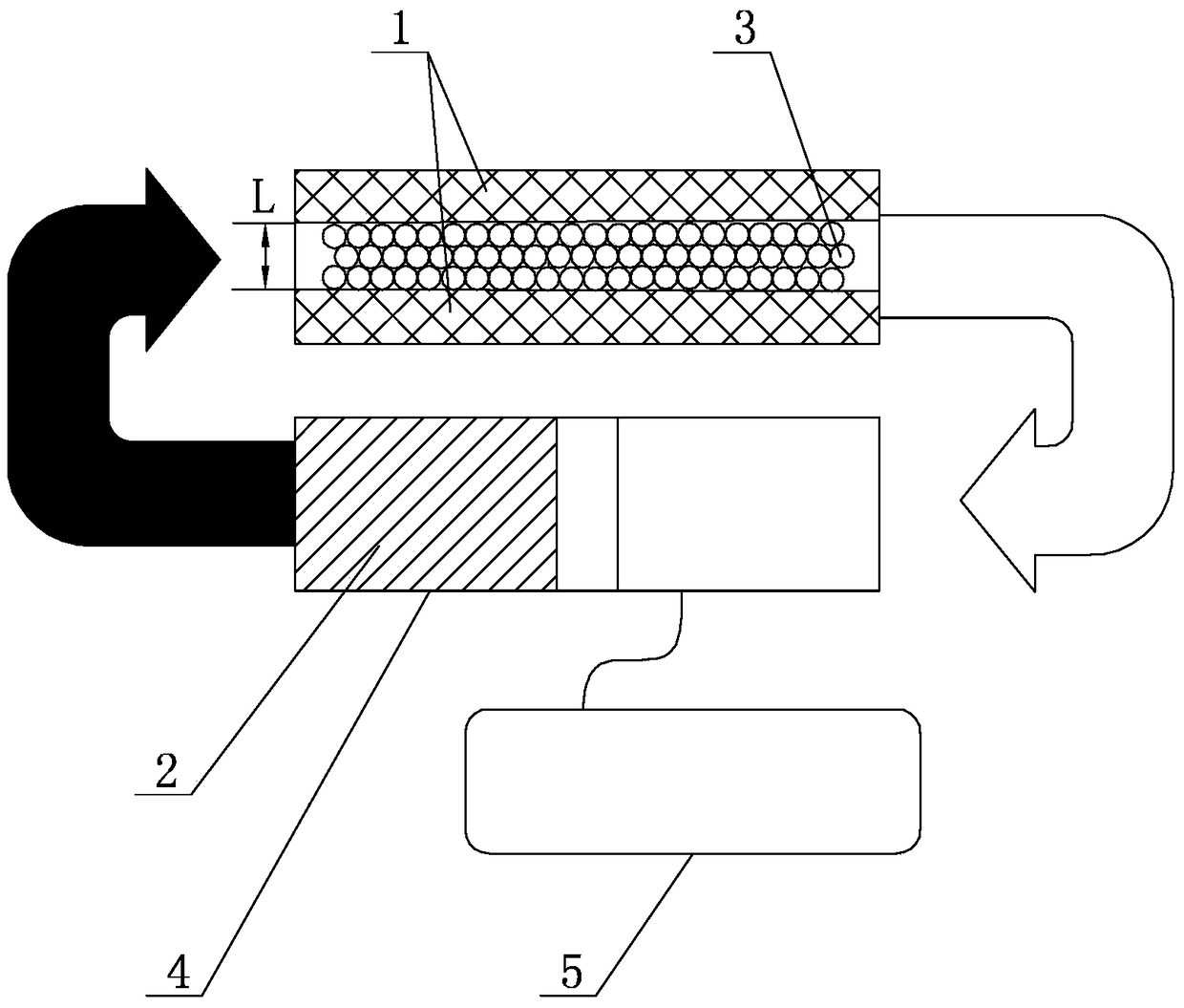
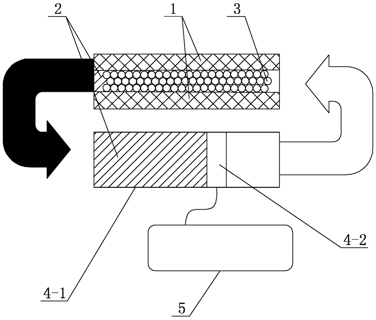
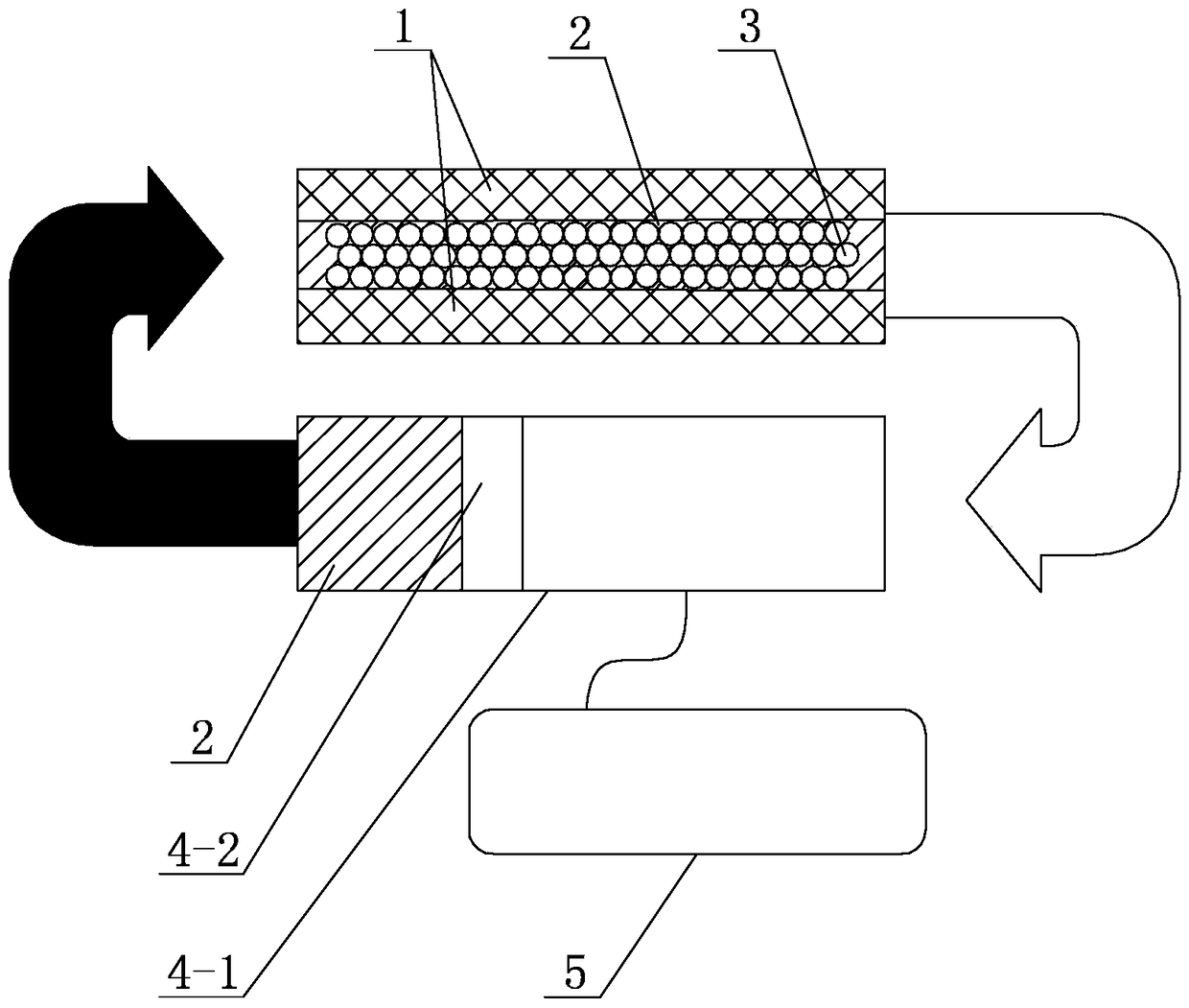
[0023] Specific implementation mode one: combine figure 1 This embodiment is described. This embodiment includes a push-pull device 4, a control assembly 5, and a vehicle window. The vehicle window includes two transparent plates 1, a filling medium liquid 2 and a plurality of medium particles 3. The two transparent plates 1 There is a gap between the two transparent plates 1, the plurality of medium particles 3 are located in the gap between the two transparent plates 1, and the filling medium liquid 2 is filled in the two transparent plates 1 for more than In the particle gap between the medium particles 3;

[0024] The push-pull device 4 includes a working cavity 4-1 and a push-pull assembly 4-2, the control assembly 5 includes a drive motor 5-1 and a controller 5-2, and the push-pull assembly 4-2 is arranged in the working cavity In 4-1, the working cavity 4-1 communicates with the gap between the two transparent plates 1, and the filling medium liquid 2 flows between the...

specific Embodiment approach 2

[0031] Specific implementation mode two: combination figure 1 The present embodiment will be described. In this embodiment, the refractive index of the filling medium liquid 2 is equal to the refractive index of the medium particles 3 . In this embodiment, the refractive index of the filling medium liquid 2 is equal to that of the medium particles 3 so that the transmission performance of the vehicle window is better, and the personnel in the vehicle can observe the scene outside the vehicle more clearly. Other structures and connections are the same as those in the first embodiment.

specific Embodiment approach 3

[0032] Specific implementation mode three: combination figure 1 This embodiment is described. In this embodiment, the refractive index of the medium particles 3 is greater than 1.4, and the particle diameter of each medium particle 3 is between 200 nm and 10 μm. The addition of a refractive index greater than 1.4, and the particle size of each medium particle 3 being 200 nm to 10 μm are the advantages brought by the present invention. Other structures and connections are the same as in the second embodiment.


PUM


Abstract

A vehicle window thermal control system and a vehicle interior temperature regulation method realized by the system, which relate to a vehicle window and a vehicle interior temperature regulation method. The invention aims to solve the problems that the existing vehicle heats up rapidly due to direct sunlight when the vehicle is parked in the open air, while the existing vehicle temperature control technology has high energy consumption, cannot work continuously and has poor flexibility. In the present invention, the working cavity communicates with the gap between the two transparent plates, the filling medium liquid flows between the working cavity and the gap between the two transparent plates, and the control signal output end of the controller is connected to the control signal input end of the drive motor, The drive signal output end of the drive motor is connected to the drive signal input end of the push-pull assembly. The method for adjusting the temperature in the vehicle of the present invention includes step 1: changing the light mode through the window into the reflected light mode through the window; and step 2: changing the reflected light mode through the window into the transmitted light mode through the window. The invention is used for cooling the vehicle.

Description

technical field [0001] The invention specifically relates to a vehicle window thermal control system and a method for adjusting the temperature inside the vehicle realized by using the system. Background technique [0002] At present, cars have become an essential tool for people to travel. With the development of China's social economy, more and more families own one or more cars. However, due to the scarcity of underground parking lots in cities, this results in a large number of open-air parking for vehicles. In the hot summer, the vehicle is exposed to direct sunlight, and the light enters the car through the window, causing the temperature inside the car to rise rapidly. Directly entering the car will cause great harm to the human body, and the extremely high temperature inside the car will also damage On-board equipment in the car. Before driving, you must use the on-board device to adjust the temperature of the car body to ensure the comfort of passengers. At the s...

Claims


Application Information

Patent Timeline
Patent Type & Authority Patents(China)
IPC IPC(8): B60J1/00B60J1/20
Inventor 李垚卢越野潘磊赵九蓬
Owner HARBIN INST OF TECH
Why Eureka
Try Eureka