Small and medium power led high power factor drive circuit

A medium and small power, driving circuit technology, applied in the direction of electric lamp circuit layout, electric light source, lighting device, etc., can solve the problems of large line power loss, low power factor, and high heat generation, so as to prolong the service life, improve the power factor, and reduce the The effect of temperature accumulation

Inactive Publication Date: 2017-07-21
南京宜海浩铭节能科技有限公司
View PDF3 Cites 0 Cited by
  • Summary
  • Abstract
  • Description
  • Claims
  • Application Information

AI Technical Summary

Problems solved by technology

At present, the drives of small and medium power LED lamps include RC step-down, isolated constant current, non-isolated constant current, etc.; RC step-down drive has a simple structure, low cost, and a power factor lower than 0.5, and the power fluctuates with the input voltage Large; isolated constant current and non-isolated constant current drives are currently the mainstream, but the power factor is less than 0.7
The power factor represents the ability of the lamp to output active power. A low power factor indicates that the power utilization rate of the LED lamp is low and the power supply loss of the line is large.
[0004] In recent years, the market demand for small and medium power LED lamps is very large, and the market is broad. However, the current small and medium power LED lamps have serious problems such as low power factor, high calorific value, and low luminous efficiency, which greatly restricts small and medium power LED lamps. development of

Method used


Image

  • Small and medium power led high power factor drive circuit
  • Small and medium power led high power factor drive circuit
  • Small and medium power led high power factor drive circuit

Examples


Embodiment Construction

[0013] The present invention will be further described in detail below in conjunction with the accompanying drawings, but the present invention shall not be limited in any way, and any changes or improvements made based on the teaching of the present invention shall fall within the scope of protection of the present invention.

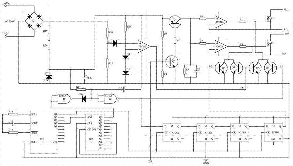
[0014] figure 1 It is a schematic diagram of the specific circuit structure of the medium and small power LED high power factor driving circuit of the present invention, according to figure 1 As shown, the specific circuit structure of the low and medium power LED high power factor drive circuit is: an external AC power supply AC 220V is connected between the positive pole of the input terminal of the bridge rectifier D1 and the negative pole of the input terminal, and the positive pole of the output terminal of the bridge rectifier D1 is sequentially connected in series. The resistor R19 and the resistor R20 are connected to the cathode of the diode D...


PUM


Abstract

The low and medium power LED high power factor driving circuit provided by the present invention can be widely applied to the field of LED applications. In specific applications, the working current of the LED lamp bead string connected to the circuit and the phase of the input AC power supply voltage tend to be synchronized, and the LED lamp The power factor of the bead string has been effectively improved, and the PF value is greater than 0.9; at the same time, the LED lamp bead string connected to the circuit is in an intermittent working state, which reduces the temperature accumulation and reduces the temperature of the LED lamp compared with the previous continuous working state. temperature, which prolongs the service life of the lamps; independent pulses drive two groups of LED lamp bead strings to emit light, realize the phase separation and superposition of the two paths of light, and improve the light efficiency of the LED lamps.

Description

technical field [0001] The invention belongs to the technical field of LED driving, and in particular relates to a driving circuit for realizing the driving of small and medium-power LED lamp bead strings by branch pulse constant current and effectively improving the power factor of the LED lamp bead strings. Background technique [0002] As a new generation of light source, LED light source is developing rapidly. LED is a solid-state semiconductor light-emitting device, which can directly convert electricity into light. It has low energy consumption, strong applicability, high stability, short response time (good switching characteristics), no pollution to the environment, and multi-color light emission. , good color rendering performance and other advantages, it is a new light source worth promoting. [0003] In LED lamps, the performance and quality of the driving circuit are very important, especially for small and medium power LED lamps, which not only require low cost...

Claims


Application Information

Patent Timeline
Patent Type & Authority Patents(China)
IPC IPC(8): H05B37/02
Inventor 王森张强
Owner 南京宜海浩铭节能科技有限公司
Why Eureka
Try Eureka