A multi-layer platform for electric equipment

A multi-layer platform and power equipment technology, applied to electrical components, substation/power distribution device casing, substation/switch layout details, etc., can solve the problems of large footprint and large device volume

Active Publication Date: 2017-07-11
XJ ELECTRIC +2
View PDF1 Cites 0 Cited by
  • Summary
  • Abstract
  • Description
  • Claims
  • Application Information

AI Technical Summary

Problems solved by technology

[0004] The purpose of the present invention is to provide a multi-layer platform for power equipment to solve the technical problems of large volume and large footprint of the device for placing power equipment and cabinets

Method used


Image

  • A multi-layer platform for electric equipment
  • A multi-layer platform for electric equipment
  • A multi-layer platform for electric equipment

Examples


Embodiment Construction

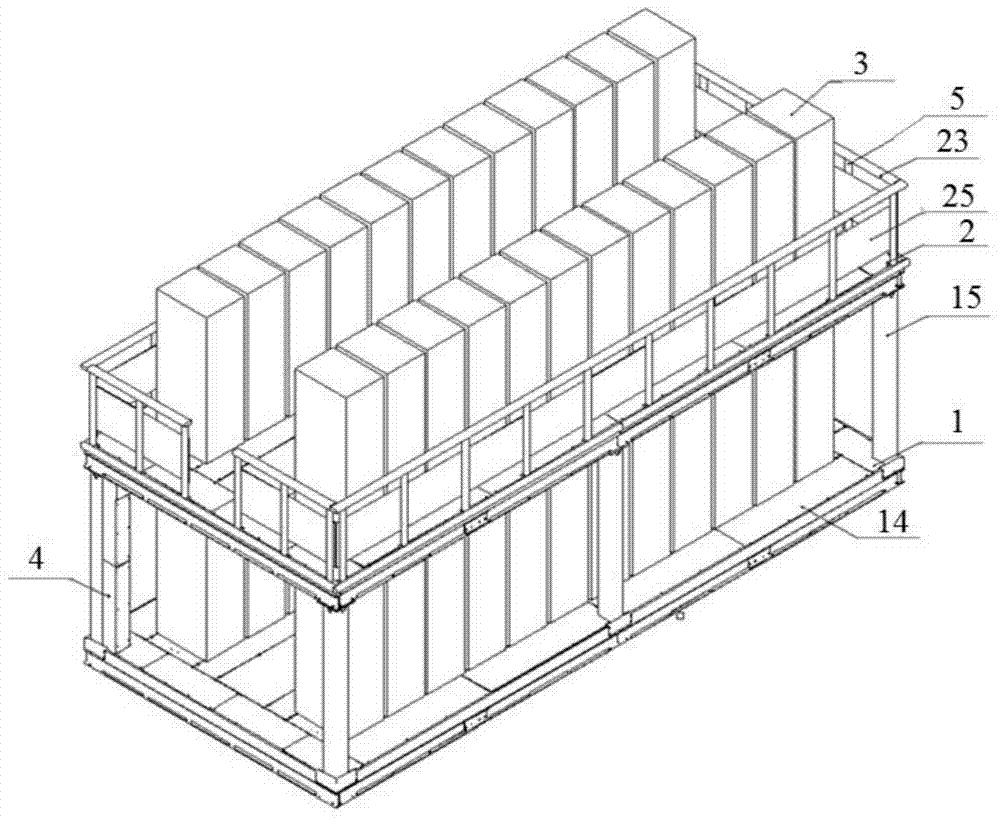
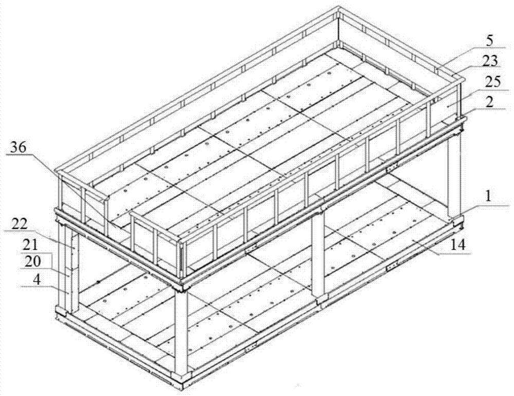
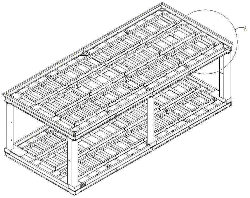
[0027] Examples of multi-layer platforms for power equipment Figure 1-10 shown.

[0028] The multi-layer platform for electric equipment includes two-layer platforms (lower platform 1 and upper platform 2 ), columns and vertical cable channels 4 with the same structure. The lower platform 1 and the upper platform 2 are fixedly supported by the four-corner uprights 15 positioned at the four corners of the two-layer platform and the center pillars 16 between the four corners. The two-layer platforms all include the bottom frame 8 , the upper part of the bottom frame 8 is provided with an upper sealing plate 14 , the lower part is provided with a lower sealing plate 37 , and a channel steel 12 is arranged between the upper sealing plate 14 and the lower sealing plate 37 . The lower sealing plate 37 and the channel steel 12 enclose the top layer cable trench 13 for cables to pass through. The side of channel steel 12 has the hole that is used for cable to pass. One side of the...


PUM


Abstract

The invention relates to a multi-layer platform for electric equipment. The multi-layer platform for power equipment includes multi-layer platforms with the same structure, uprights and vertical cable channels; the two adjacent platforms are fixed and supported by the uprights; each layer of platforms includes a bottom frame and an upper part of the bottom frame. The top cable trench; at least one side of the top cable trench is provided with an installation position for placing the cabinet; the vertical cable channel is located between two adjacent platforms, and the upper and lower ends of the vertical cable channel are respectively connected to the The upper platform communicates with the top floor cable trench of the lower platform. The multi-layer platform for electric equipment provided by the invention realizes the multi-layer placement of cabinets and the connection of cables between the platforms of each layer, which can effectively save space and reduce the occupied area.

Description

technical field [0001] The invention relates to the field of electric equipment, in particular to a multi-layer platform for electric equipment. Background technique [0002] At present, in the power system, the devices for placing various power equipment and cabinets are usually box-type structures, and the arrangement method usually adopts a single-layer arrangement. This single-layer box-house structure has the disadvantages of large volume and large footprint, which is not conducive to transportation and construction. [0003] For example, the authorized announcement number is CN 203787827 U, and the Chinese patent office named metal armored box-type substation discloses a box-type substation. Panels and other modules spliced ​​together. This kind of box room structure adopts a single-layer layout, which cannot meet the application in the case of limited site area. Contents of the invention [0004] The purpose of the present invention is to provide a multi-layer pl...

Claims


Application Information

Patent Timeline
Patent Type & Authority Patents(China)
IPC IPC(8): H02B1/30H02B1/01
Inventor 杜永平张东勇王卫红张香芍张桂如高颖旭王皓翔王华伦杜永祥董会平张培锋张朝相张好涛熊卫斌
Owner XJ ELECTRIC
Why Eureka
Try Eureka