
Angular point positioning method and apparatus

A positioning method and technology of a positioning device, which are applied in image data processing, instruments, calculations, etc., can solve the problems of unable to directly obtain the coordinates of the corner points to be matched, affecting the accuracy of image matching, reducing the accuracy of the mechanism system, etc. operation, improve accuracy, and improve the effect of system accuracy

Active Publication Date: 2015-11-18
SHENZHEN HUAHAN WEIYE TECH
View PDF3 Cites 45 Cited by
  • Summary
  • Abstract
  • Description
  • Claims
  • Application Information

AI Technical Summary

Problems solved by technology

However, these two methods can only obtain the coordinates of the center of the region of interest after matching, and cannot directly obtain the coordinates of the corner points to be matched
If you want to obtain the coordinates of the corner points, you need to add a preset offset to the coordinates of the center of the region of interest, and the setting of the offset basically depends on manual settings, thus affecting the accuracy of image matching , greatly reducing the system accuracy of the mechanism

Method used


Image

  • Angular point positioning method and apparatus
  • Angular point positioning method and apparatus
  • Angular point positioning method and apparatus

Examples


Embodiment 1

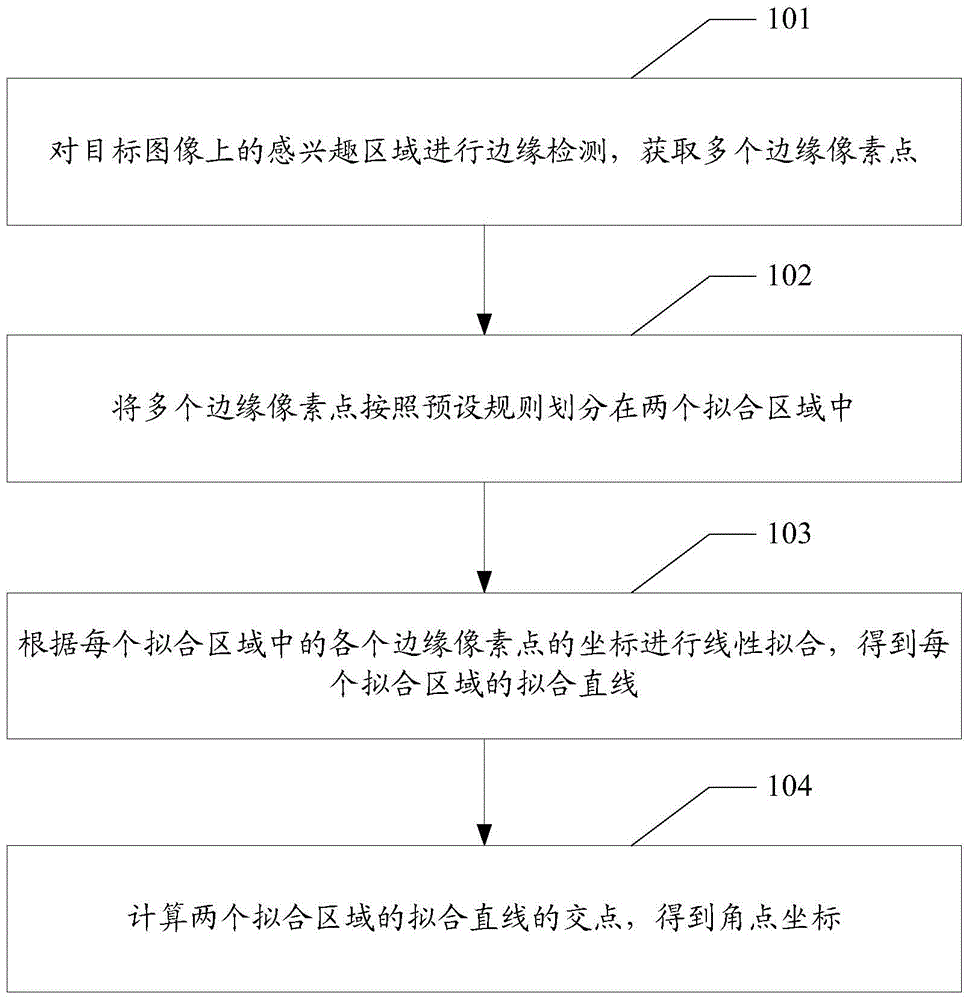
[0029] Please refer to figure 1 , figure 1 It is a flow chart of the method in Embodiment 1 of the present invention. Such as figure 1 As shown, a corner positioning method may include the following steps:

[0030] 101. Perform edge detection on the region of interest on the target image, and acquire multiple edge pixels.

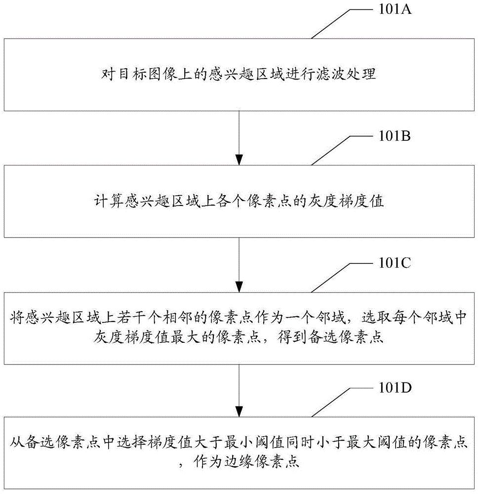
[0031] In one embodiment, such as figure 2 As shown, step 101 may specifically include the following steps:

[0032] 101A. Perform filtering processing on the region of interest on the target image.

[0033] The filtering process can remove the noise in the region of interest, which can reduce the error caused by the noise in the subsequent positioning and improve the positioning accuracy.

[0034] 101B. Calculate the gray gradient value of each pixel in the region of interest.

[0035] It can be understood that the image edge usually concentrates most of the detection information of the image. Therefore, when identifying the entire image scene and ...

Embodiment 2

[0084] Correspondingly, this application also provides a corner positioning device, please refer to Figure 8 , Figure 8 It is a schematic diagram of the device structure implemented by the present invention. Such as Figure 8 As shown, the corner positioning device may include:

[0085] The edge detection unit 30 is configured to perform edge detection on the region of interest on the target image, and acquire a plurality of edge pixels.

[0086] The division unit 31 is configured to divide the plurality of edge pixel points acquired by the edge detection unit 30 into two fitting areas according to preset rules.

[0087] The linear fitting unit 32 is configured to perform linear fitting according to the coordinates of each edge pixel point in each of the fitting regions divided by the dividing unit 31 to obtain a fitting straight line of each fitting region.

[0088] The corner point determining unit 33 is configured to calculate the intersection of the fitting straight ...


PUM


Abstract

According to an angular point positioning method and apparatus which are provided by the present invention, firstly, an interest area on a target image is subjected to edge detection to acquire a plurality of edge pixel points, then the plurality of edge pixel points are partitioned into two fit areas according to preset rules, coordinates of each edge pixel point in each fit area is subjected to linear fitting to obtain two fitting straight lines and finally, angular point coordinates can be obtained by calculating a point of intersection of two fitting straight lines, and thus, in the image matching process, the required angular point position can be accurately positioned without manually presetting an offset and not only the manual operation is reduced, but also accuacy of angular point positioning and image matching is greatly promoted, so that system accuracy of a mechanism is promoted.

Description

technical field [0001] The present application relates to a corner point positioning method and device. Background technique [0002] At present, image matching usually uses a smaller image as a template image, and compares the template image with the target image to determine whether there is an identical or similar region to the template in the target image. When there are identical or similar regions, the positions of these identical or similar regions can be determined and extracted by matching with the template image. Usually, the position coordinates extracted by image matching are mapped to the machine coordinate system through affine transformation to control the movement of the mechanism. Therefore, the matching accuracy will affect the motion accuracy of the machine tool. In some alignment and fitting scenarios, such as the fitting process of mobile phone screens, since the processed objects are small, and usually the fitting requirements reach an accuracy of 0.1...

Claims


Application Information

Patent Timeline
IPC IPC(8): G06T7/00
CPCG06T7/001G06T2207/10004G06T2207/30108
Inventor 杨洋康智远
Owner SHENZHEN HUAHAN WEIYE TECH
Learn More