
Rotary kiln shovel plate lifting detection device

A detection device and shovel plate technology, which are applied in the directions of rotary drum furnaces, furnaces, lighting and heating equipment, etc., can solve the problems of material leakage, material leakage at the connection between the shovel plate and the chain grate machine, production shutdown and maintenance, etc., to reduce the The effect of trouble and economic loss, improving work efficiency, and broad market prospects

Active Publication Date: 2017-03-01
MCC NORTH (DALIAN) ENG TECH CO LTD
View PDF5 Cites 0 Cited by
  • Summary
  • Abstract
  • Description
  • Claims
  • Application Information

AI Technical Summary

Problems solved by technology

[0004] However, after many on-site investigations and summaries, material leakage at the joint between the shovel plate and the grate has almost always occurred during commissioning and production. Once material leakage occurs, it is difficult for workers to find out in time because there is no detection and alarm device. , and it is also difficult to judge which shovel plate is lifted, let alone take corresponding measures. As a result, a large amount of material leakage will occur, and even production will be stopped for maintenance, which restricts the total output of the pellet production line and becomes a problem for the entire process. It is an intermediate bottleneck of the process, so it is particularly important to ensure the stable and continuous production of the pellet production line, and timely and accurately detect the position of the scraper plate of the rotary kiln during the production process

Method used


Image

  • Rotary kiln shovel plate lifting detection device
  • Rotary kiln shovel plate lifting detection device
  • Rotary kiln shovel plate lifting detection device

Examples


Embodiment Construction

[0017] The specific implementation manner of the present invention will be further described below in conjunction with the accompanying drawings.

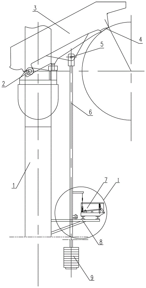
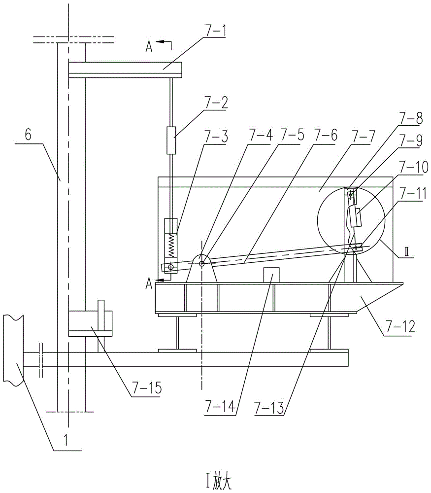
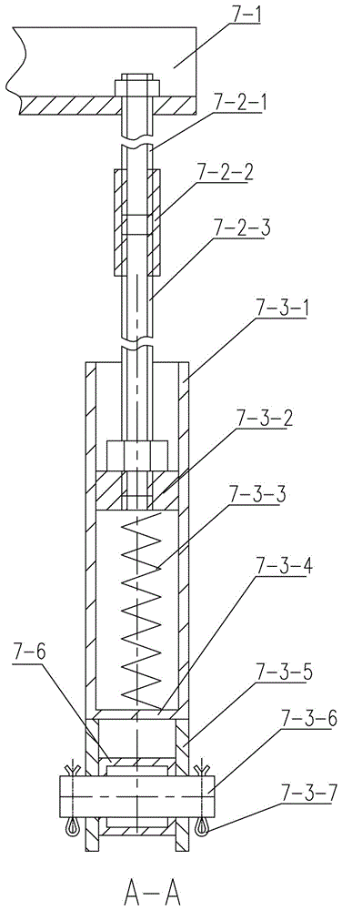
[0018] Such as figure 1 , 2 As shown, the lifting detection device of the rotary kiln shovel plate of the present invention includes a DCS system, a fixed frame 1 rotatably connected to the lower part of the shovel plate 3 and a counterweight boom 6 rotatably connected to the lower part of the shovel plate 3 , the counterweight boom 6 is hinged with the shovel plate 3 through the rotating shaft 5, the shovel plate 3 can rotate around the support shaft 2, and at the same time drives the counterweight boom 6 to move up and down. 9 to maintain the connection with the grate machine, the arc surface 4 on the shovel plate 3 is a shovel point, and it is characterized in that: a cantilever support 8 is provided on the fixed frame 1, and the cantilever support 8 is provided with The shovel plate detection device 7, the shovel plate detect...


PUM


Abstract

The invention belongs to the technical field of working fault detection of rotary kilns of chain-and-grid conveyers and particularly relates to a lifting detection device for a spading plate of a rotary kiln. The lifting detection device comprises a distributed control system (DCS), a fixing rack and a balance weight suspender. A cantilever support is arranged on the fixing rack and provided with a spading plate detection device. The spading plate detection device is composed of a limiting guide seat, a bracket, a hinge seat, a limiting block, a sensor support, a rotary shaft, a rotary rod, an elastic stretching device, a linear displacement sensor, an alarming device, a spiral tensioner, a servo level hanging bracket and a dust cover. The spiral tensioner is composed of a right-handed thread pull rod, a double nipple and a left-handed thread pull rod. The geometric similarity principle is applied to the mechanical structure, rotary points with unequal two-end distances are arranged on the rotary rod, small-distance lifting at one end is amplified to large-distance lifting at the other end in a multiplied mode, and the linear displacement sensor transmits signals to the DCS. The working state of the spading plate can be accurately grasped, and alarms are given in time once abnormalities occur

Description

technical field [0001] The invention belongs to the technical field of working fault detection of a rotary kiln with a grate machine, and in particular relates to a lifting detection device for a shovel plate of a rotary kiln. Background technique [0002] With the rapid development of my country's iron and steel industry, more and more domestic iron and steel enterprises adopt the grate-rotary kiln method to produce oxidized pellets. At the same time, the production scale has gradually expanded from the annual output of hundreds of thousands of tons to the current several million tons. , which fully embodies the advantages of the grate-rotary kiln method with advanced technology, excellent quality, high output, and excellent benefits. [0003] During the production process of the pelletizing plant, the shovel plate is the connecting equipment between the two main machines (the grate machine and the rotary kiln), and the pellets treated (dehydrated and preheated) on the chain...

Claims


Application Information

Patent Timeline
Patent Type & Authority Patents(China)
IPC IPC(8): F27B7/42
Inventor 王志国张维超
Owner MCC NORTH (DALIAN) ENG TECH CO LTD
Learn More