
Shear wall with continuous zigzag tie bar structure

A zigzag and shear wall technology, applied to walls, building components, building structures, etc., can solve the problems of insufficient constraints of vertically distributed tendons, large steel consumption, and inability to improve the ductility of shear walls, etc., to achieve Low cost, improved ductility, and the effect of preventing steel bars from overturning

Inactive Publication Date: 2015-11-18
GUANGZHOU DESIGN INST
View PDF7 Cites 2 Cited by
  • Summary
  • Abstract
  • Description
  • Claims
  • Application Information

AI Technical Summary

Problems solved by technology

[0006] The purpose of the present invention is to solve the problems in the prior art that there is a large amount of steel used and the tension bars and horizontal distribution bars are insufficient to restrain the vertical distribution bars, which cannot improve the ductility of the shear wall. shear wall

Method used


Image

  • Shear wall with continuous zigzag tie bar structure
  • Shear wall with continuous zigzag tie bar structure
  • Shear wall with continuous zigzag tie bar structure

Examples


specific Embodiment 1

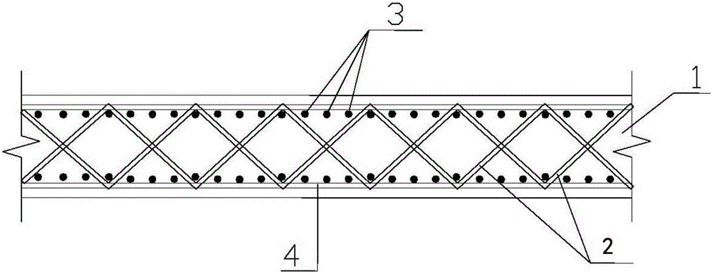
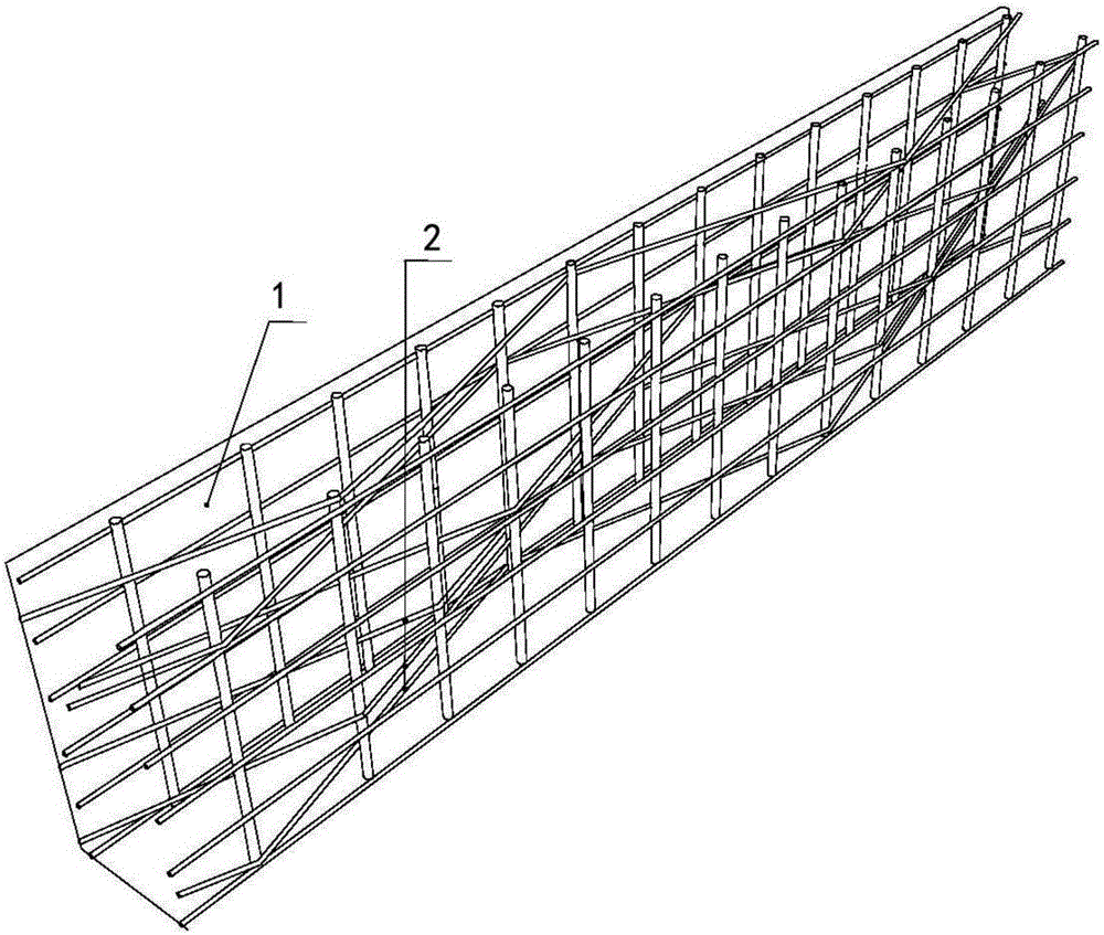
[0024] refer to Figure 1 to Figure 3 , this embodiment includes a concrete wall 1 and a steel bar structure built in the concrete wall 1, the steel bar structure is formed by connecting several tie bars 2, several vertically distributed bars 3 and several horizontally distributed bars 4, so The vertically distributed ribs 3 are vertically arranged in two rows in parallel, and the zigzag-shaped tendons 2 are arranged in the two rows of vertically distributed ribs 3 from top to bottom. 3 fixedly connected to form a three-dimensional frame structure; the horizontal distribution bars 4 are arranged on the outside or inside of the vertical distribution bars 3 from top to bottom, and one or more zigzag bars 2 are arranged The sharp points of 2 are fixedly connected with adjacent horizontal distribution ribs 4 to form a three-dimensional shear wall truss structure with one or more layers of horizontal frame structures.

[0025] In this example:

[0026] In the zigzag ties 2, in th...

specific Embodiment 2

[0031] refer to Figure 4 The characteristics of the specific embodiment 2 of the present invention are: the zigzag-shaped tie bars 2 are composed of several sections of V-shaped tie bars, and the lengths of the two sides of each V-shaped tie bar meet the overlapping length, and are formed by welding or mechanical connection. Make each section of V-shaped tie bars form a continuous zigzag tie bar. Welding or mechanical connection is used to make each section of V-shaped tie bars form a continuous zigzag tie bar. All the other are with specific embodiment 1.


PUM


Abstract

The invention relates to a shear wall with a continuous zigzag tie bar structure. The shear wall comprises a concrete wall body and a steel bar structure built in the concrete wall body, and is characterized in that the steel bar structure is formed by connecting a plurality of tie bars, a plurality of vertical distribution bars and a plurality of horizontal distribution bars; the vertical distribution bars are vertically and parallelly ranged into two rows; zigzag tie bars are arranged in the two rows of vertical distribution bars from top to bottom; a cuspidal point of each zigzag tie bar is fixedly connected with the vertical distribution bars to form a three-dimensional framework structure; the horizontal distribution bars are arranged at the outer side or the inner side of the vertical distribution bars from top to bottom; and in the zigzag tie bars, the cuspidal point(s) of one or a plurality of zigzag tie bars is(are) fixedly connected with the adjacent horizontal distribution bars to form a three-dimensional shear wall truss structure with a one-layer or multi-layer horizontal frame body structure. The shear wall can solve the problems that the steel consumption is great; the restriction of the tie bars and the horizontal distribution bars on the vertical distribution bars is insufficient; and the effect of improving the ductility of the shear wall cannot be achieved. The shear wall has the beneficial effects that the steel bar overturning in the construction period can be prevented; the cost is low; and the ductility is high.

Description

technical field [0001] The invention relates to a shear wall, in particular to a shear wall with a continuous zigzag lacing structure, and belongs to the technical field of building structures. Background technique [0002] At present, shear walls are formed by pouring concrete on the basis of steel cages. Since the vertically distributed reinforcement is in a cantilever state when making the reinforcement cage, it is easy to topple over and affect the construction. [0003] In the prior art, it is generally adopted to increase the size of the vertical reinforcement to solve this problem, that is, the diameter of the vertical distribution reinforcement is required to be not less than 10mm; however, this requirement not only increases the steel consumption, but also does not fundamentally Above all, it solves the problem that the vertical distribution bars are always in a cantilever state, so that the lead wires fall over, and the effect of preventing the overturning of the ...

Claims


Application Information

Patent Timeline
Patent Type & Authority Applications(China)
IPC IPC(8): E04B2/56
Inventor 王一功米强韩建强
Owner GUANGZHOU DESIGN INST
Learn More