
Automatic edge control device of industrial sewing machine

An industrial sewing machine and automatic technology, applied in sewing equipment, sewing machine components, cloth feeding mechanism, etc., can solve the problems of inability to use computer programs and servo motors, poor sewing effect, high cost investment, etc., and achieve simple structure and small investment , the effect of reducing labor intensity

Active Publication Date: 2015-11-18
SHANGHAI WEISHI MACHINERY
View PDF10 Cites 8 Cited by
  • Summary
  • Abstract
  • Description
  • Claims
  • Application Information

AI Technical Summary

Problems solved by technology

However, when the edge of the fabric to be sewn is arc-shaped or other irregular lines, it is more difficult to control the edge manually, the sewing effect is poor, and the consistency is low
[0004] However, relying on computer programs and servo motors to control the sewing trajectory requires a large cost investment, and is suitable for mass production of special parts, such as patch pockets on shirt pockets, and for some customized, non-batch clothing, or personalized For edge parts with a high degree of irregular curves, it is generally impossible to use computer programs and servo motors to control the sewing trajectory

Method used


Image

  • Automatic edge control device of industrial sewing machine
  • Automatic edge control device of industrial sewing machine
  • Automatic edge control device of industrial sewing machine

Examples


Embodiment Construction

[0020] The present invention will be further described below in conjunction with the drawings and specific embodiments.

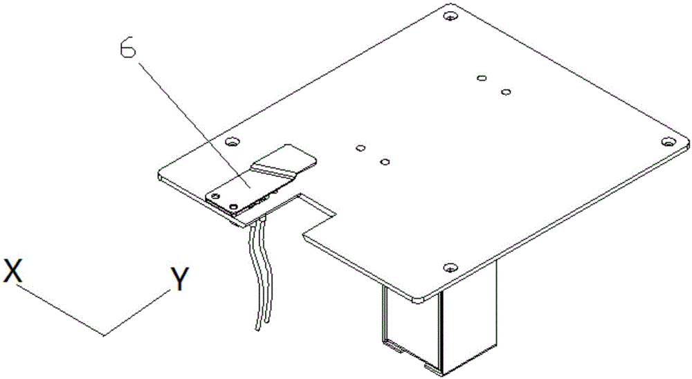
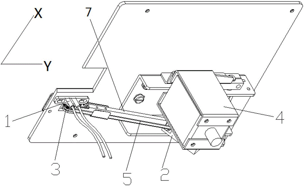
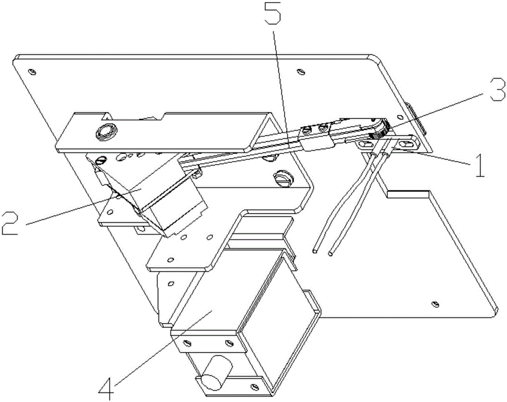
[0021] See Figure 1-Figure 3 , An automatic edge controller of an industrial sewing machine, comprising a platform on which a material pressing plate 6 is fixed; the sewing material feed direction is the X direction, and the horizontal and vertical direction is the Y direction; the lower part of the platform is fixedly provided with a motor 2. Electromagnet 4, the motor drives the timing belt 5 to rotate. The timing belt 5 is installed on the rigid rocker arm 7, and the ejector rod of the electromagnet 4 lifts the rigid rocker arm 7 upwards, so that the upper end of the ratchet 3 presses the cloth on the press On the lower end surface of the material plate 6, the friction force between the sewing material and the pressing plate 6 is much smaller than the friction force between the ratchet wheel 3 and the cloth; a pair of photoelectric switches 1 are provided o...


PUM


Abstract

The invention relates to an automatic edge control device of an industrial sewing machine. The automatic edge control device comprises a platform, and a pressing plate is fixedly arranged on the platform. The feeding direction of sewing material is the X direction, and the direction perpendicular to the horizontal direction is the Y direction. A motor and an electromagnet are fixedly arranged on the lower portion of the platform, the motor drives a synchronous belt to rotate, the synchronous belt is installed on a rigid rocker arm, an ejector rod of the electromagnet ejects the rigid rocker arm up, the upper end of a ratchet presses cloth on the lower end face of the pressing plate, and friction force between the sewing material and the pressing plate is much smaller than that between the ratchet and the cloth. A pair of photoelectric switches are arranged at the parts, close to the sewing portion, of the platform in the Y direction; when the photoelectric switch on the inner side can not detect the sewing material, the motor works in the forward direction, and the synchronous belt drives the ratchet to rotate in the forward direction so that the sewing material can move outwards. When the photoelectric switch on the outer side senses the sewing material, the motor works in the backward direction, the synchronous belt drives the ratchet to rotate in the reverse direction until the photoelectric switch on the outer side can not sense the sewing material, and then the motor stops working.

Description

Technical field [0001] The invention relates to an industrial sewing machine, in particular to an automatic edge controller of an industrial sewing machine, belonging to the technical field of industrial sewing machine edge control. Background technique [0002] Existing industrial sewing machines, in the process of sewing the edge of the fabric, some control the edge according to the "backer", and some rely on computer programs and servo motors to control the sewing track. [0003] When the edge of the fabric to be sewn is in a straight line, the "backer" is used for alignment, and the edge can be manually controlled, and the effect can also meet the general requirements. But when the edge of the fabric to be sewn is arc-shaped or other irregular lines, it is more difficult to manually control the edge, the sewing effect is poor, and the consistency is low. [0004] The way of relying on computer programs and servo motors to control the sewing track requires a large cost investment...

Claims


Application Information

Patent Timeline
IPC IPC(8): D05B35/10
Inventor 刘世振狄金刚柴国宣
Owner SHANGHAI WEISHI MACHINERY
Learn More